32. Remove D pillars by undoing (2) phillips screws shown above and then popping it out using a panel removal tool. You can then pop out the rear seat recline switch (if equipped) and unplug it by using a slotted screwdriver to slide up the plug carrier.
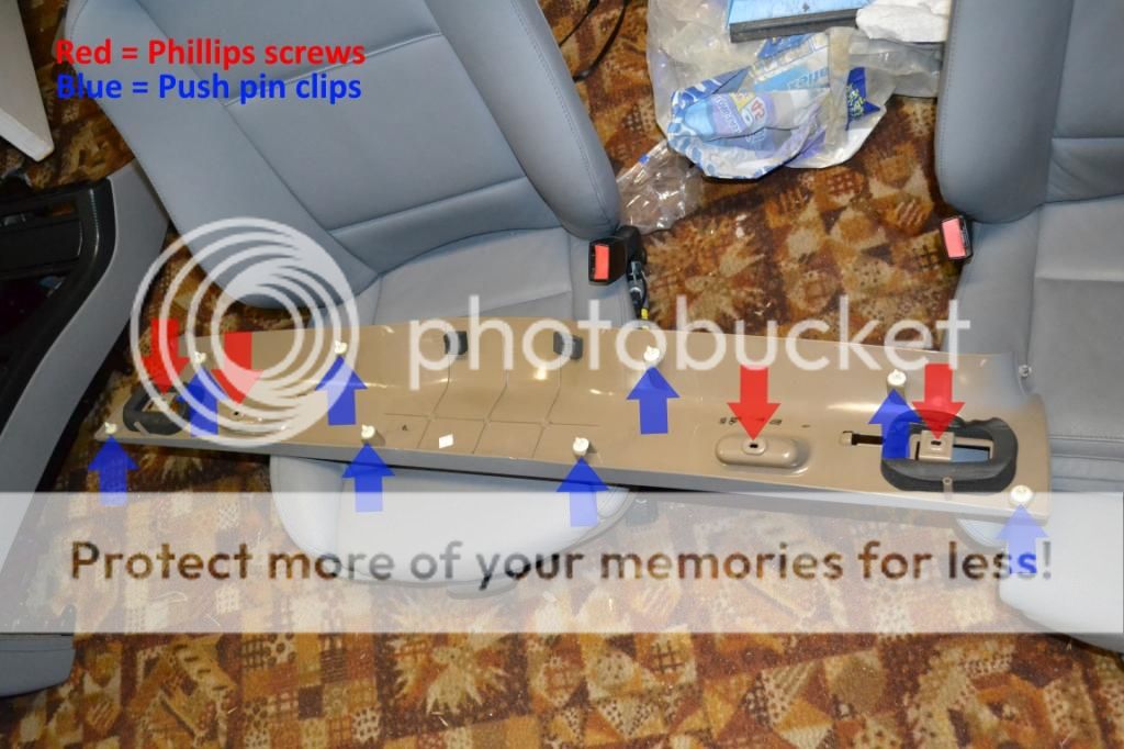
33. Now you can remove all the rear lift gate plastic trims. The sides are first and then the rear/bottom. You will most likely break 1 push pin style piece on the side trims. I found this to be unavoidable no matter how careful I was with my prying. YMMV though and hopefully yours comes out with no damage. You will need to remove and disconnect the lift gate lights before removing the rear section. Then undo (4) phillips screws and the bottom trim panel will pop off with a series of (8) push pins.

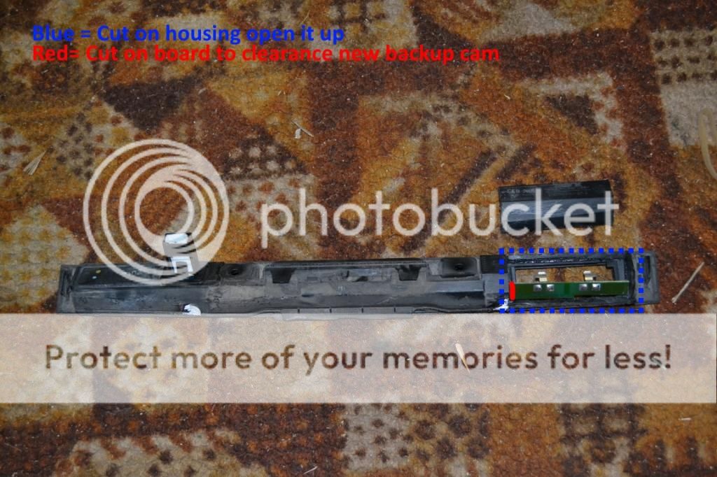
34. Remove the rear license plate light housing by unscrewing (4) T20 torx screws and unplugging the 4 pin connector shown below in step 35. This connector is where you will tap in your new LED light wires on the inside of the lift gate after mounting the camera to the license plate light housing. 35. Break out your dremel as both the factory housing and the new camera need to be modified in order to work together. First, disassemble your factory housing by releasing the 4 plastic clips holding the 2 halves together. This can be challenging but is definitely possible using two or three slotted screwdrivers with a plastic panel pry tool. Remove the passenger side lens.
36. Now cut the passenger side rear of the black plastic section as shown. Try to be as clean as possible as this will make it easier to reassemble and seal later. There are seam lines to follow to aid in ensuring a mostly straight cut. I used a dremel with a cutoff wheel to do mine. Cut is shown in step 37 picture.
37. With that section opened up you can see the circuit board that goes through there to hold the light bulbs. This needs to be removed for clearance of the new unit (cut shown above). Cut the circuit board as close to your housing cut as possible as you will not need access to it going forward. Don't worry about polarity, I tested all that prior to disassembly and will provide where to tap your new LED leads into later in the guide.
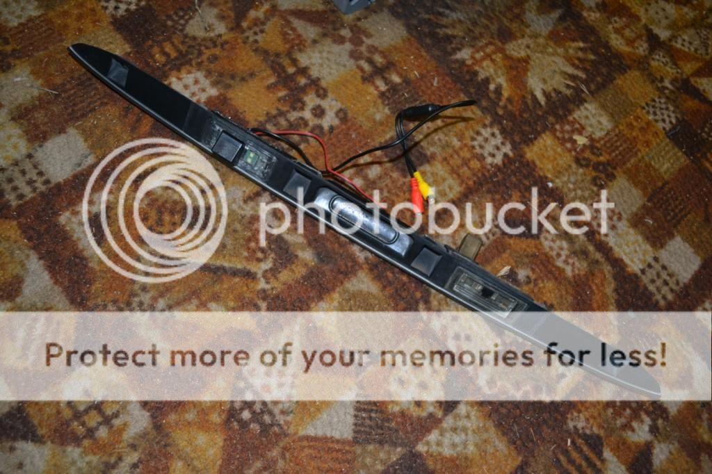
38. Now you have to trim your new camera/lens to fit the factory opening. I cannot tell you exactly how to do this as it involves many test fits, trims, and more test fitting. I will tell you it is a considerable amount of trimming. Unfortunately I did not take a picture of the finished trimmed camera housing but you will see what needs to be done when you test fit it.
39. Once you have it fitting to your satisfaction use hot glue in a couple of areas to hold it in place. This is NOT a permanent mounting solution. Go around your unit with the silicon of your choice (Permaseal in my case) and once it cures will be a permanent mount and sealing solution. Now this does mean it would not be easy to replace the camera should it go bad, so bear that in mind. I ordered it thinking it would be a direct fit... boy was that wrong. I will be imploring AvinUSA to change their item description for this particular camera to reflect that it does not fit the e53.
40. Now drill a hole in the black plastic piece you cut out in step 36 large enough to pass the wires through (shown in step 35 picture). Once that is done you can hot glue (to hold in place) the piece back in place. Just spot glue it in a few places and then go around the whole thing with your silicon to create a permanent bond and seal. Go ahead and also pump the hole where the wires pass through with hot glue to hold and seal those. This is not crucial which is why I only used the hot glue and not the silicon too.
41. Go ahead and extend all the wires coming off the camera now (power, ground, etc) by soldering or crimping additional lengths of wire to them. I chose to trigger my camera (yellow wire on RCA) with the same wire as the power so they were soldered together. Now comes the hardest pill to swallow of the whole camera installation... drilling a hole into your lift gate. You need to pass the wires through into the lift gate just like the factory does it on the driver's side with a square hole. I went over and over this to see if there was a way to run wires through the license plate light holder in order to utilize the factory hole... short answer, there is no easy way to do this. It's easier to just drill the hole. Make it just big enough for the wires to pass (video wire is the largest to accommodate, insert it first). Put some paint (touch up paint works great), silicon, or grease on the metal to prevent any corrosion.
42. Plug all your wires into the camera and run them to the passenger side, there are 2 holes there for the wires to pass out of the rear compartment. You will notice that I use heat shrink over all my RCA connections and any connection really that can be pulled apart. This ensures no accidental disconnection is going to happen during install, or further down the road. Sorry, I don't have a picture of the drilled hole but can get one and revise this if requested.
43. Go ahead and reinstall the rear license plate housing now (4) T20 torx screws while pulling the excess wire slack through at the same time. Run only the 2 wires you extended for the license plate lights over to the 4 pin harness (X1739) that supplies the OEM license plate lights. The wires you want to tap are: brown (ground) and Green/Orange (+12v to passenger side plate light). Secure all your wires to the OEM harnesses.
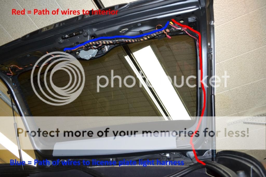

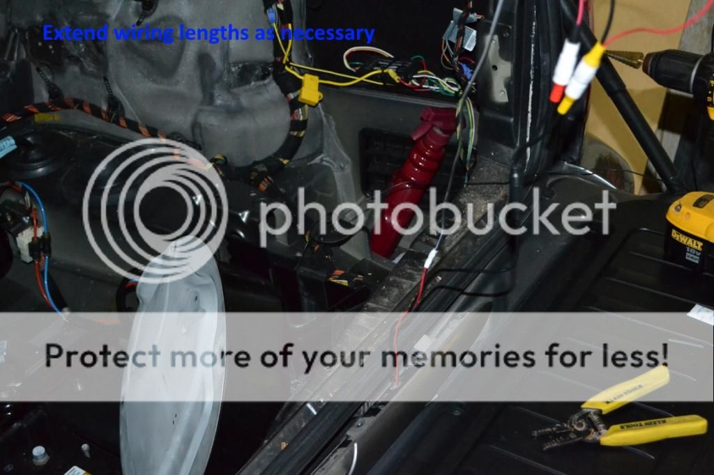
44. Now you have power/ground for the camera and the video signal wire to pass along the passenger side harness to the rubber "snake" grommet that goes from the lift gate to the body of the vehicle. You will most likely have to cut the video signal RCA (I re-soldered/insulated it later) in order to fit it through the grommet. I accomplished this task by using a combination of a long zip tie that I could tape my wires to and pull through the grommet and a long "grasp" tool that can be inserted in one direction and then pulled back out with the grasper on the new wires. The wiring path is shown in image from previous step.
45. Once you have the wires through the factory grommet and into the vehicle you can run it down along the D pillar area until you get to the fuse box area. At this point you will see a factory ground point (pictured in step 53 image) in front of the fuse box area. Run your wires along the factory harness behind the fuse box and secure with zip ties. Go ahead and separate the positive wire for the camera (we'll come back to it later) from the negative wire at this point. Cut the negative wire to reach the factory ground point with 3-4 inches of extra length. Don't terminate it yet. I grounded the parking wire (for video in motion) to this location as well, just in case it was necessary. I have read you don't need to use the parking wire, but I used it anyway and soldered both wires to a ring terminal and installed them along with the factory grounds. Your yellow RCA will join your main cable run to the front here (shown in red below).
46. Go ahead and reinstall all of your lift gate trims. We are done back there. Install rear section first (4) phillips screws and pops into place. Then install the 2 sides using a series of push clips. Reinstall the lift gate courtesy lights and emergency hatch release plastic pull.
47. This step will have sub-steps and involve the creation of a control "circuit" for the backup camera. There are easier ways to do this using a standard bosch 5 pin style relay and triggering it with the backup lights. This is not your average DIY though so I am going to show you a cooler way which I cannot take credit for. Thanks to TerminatorX5 for the legwork/info and Smokey53 (both from Xoutpost) for the nudge in this direction. What we are doing is making a simple control circuit so that the factory Park Distance Control system controls the rear camera like a factory setup would. Manual control is possible as well utilizing the factory PDC switch.
a) From Radio Shack you will need model #275-241 micro relay. You will also need project box model #270-1801 to house the circuit. You can also buy the bread board from radio shack as well but will have to trim it to fit the box. You won't need much. Solder/soldering iron are also a must for this mod. If you don't have extra wire lying around, buy some 18 gauge speaker wire as well. Get some in different colors as you will have 4 wires coming out of the box you need to distinguish.
b) First thing you will need to do is trim up your bread board to fit inside the project box. I used a dremel to cut some and get it to fit in there. You can use the 4 mounting locations to secure it to the box, but unfortunately these screws are not included so you will have to pick some up or use some from a stash you have like I did.
c) Now, plan out where you are going to mount all of your components. You can use my picture as a guide if you want. This is probably not the best layout for the circuit but works fine. I put a diagnosis LED on there with a resistor but you can skip this. I had a bunch of red LEDs lying around and thought it would be nice if the circuit would tell me if it is in use. Omit the connections from the LED if not using one.
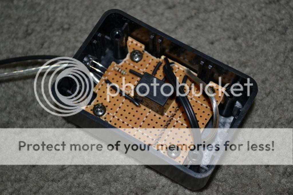
d)The diagram for this circuit is below, and a pinout for the relay to make things easier to understand. Solder up your board accordingly. As I said you can skip the LED/resistor combo if you like. It is not necessary to the circuit. After you are done, you can test the circuit using a 9v battery and multimeter just to make sure you have everything good to go before putting it in the vehicle.

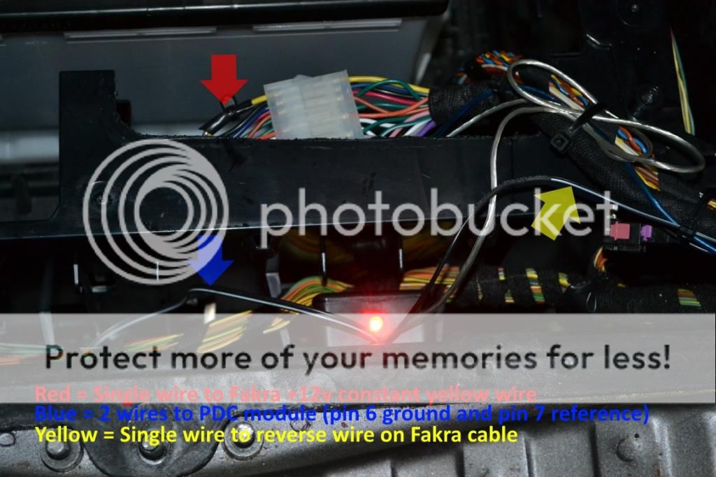
e) You should be left with 4 wires coming out of the project box. The NC pin (normally closed) will not be used for anything. The 2 coil wires (represented by coiled lines on the package diagram the relay came in) are for PDC reference source (pin 7 Brown/White or Brown/Yellow wire) and for ground (pin 6 ) coming off the PDC module's second (Black X300 plug) harness. It doesn't matter which side of the coil is for which... it doesn't care about polarity so solder it whichever way makes building the rest of the circuit easier. 12v (battery) constant can be pulled from the Fakra yellow wire (silver wire coming out of box shown below). The final wire coming out of the project box is the NO (normally open pin) and goes to the Fakra reverse input wire. This is the wire that gets switched to 12v when the PDC is turned on... either by the car or by you with the button. You also need to tie your camera positive wire (that was left from step 45) AND your yellow RCA trigger wire to this wire. If you are using the same setup as me it means you have to run an additional small gauge wire along with your yellow RCA wire all the way to the front of the car. If you are using a trigger wire separate from your RCA video wire you can skip running the extra wire. Your new control box can easily be tucked with the rest of the modules in the tray as shown below. The module on the left with the 3 plugs is the PDC module.
I realize that all of that might be hard to understand and sound daunting, but if you follow the diagram and instructions it's not too bad. It took me 20 times longer to write it than to do it.
Wiring the Avin and Accessories
48. To access the factory radio unit (the actual radio, not the screen) we need to remove the plastic cover around the battery: (1) 13mm nut and (3) phillips screws. Now remove (4) phillips screws to remove the module/electronics bracket. Loosen (1) 8mm nut and you can remove the factory radio from the bracket. Go ahead and connect your Avin Fakra cable to the radio harness.

49. There are 3 wires coming off the Fakra that need to be addressed: parking, reverse, and amp continuous. If you are not planning on installing aftermarket amplifiers in the future you can disregard the amp cont. I have READ that you can disregard the parking wire as well. I went ahead and grounded it just to be on the safe side. The reverse wire was addressed in step 47 and comes from the control circuit. All of these connect using wires soldered to appropriately sized bullet style connectors.

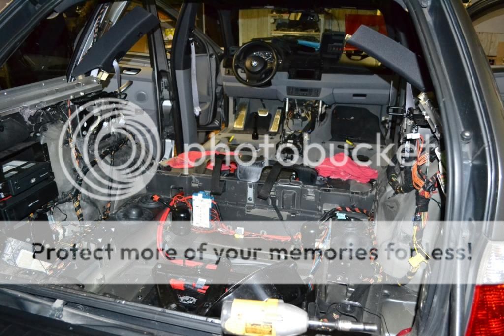
50. Now is the time to decide if you are running any additional accessories in the future. I ran 3 pairs of RCA's and a remote wire for future audio upgrades (the copper colored wires shown after step 53). These RCAs have to go from the factory amp location (in my case) all the way to the front of the truck and I didn't want to have to pull it apart again in the future. BTW, I chose the run the wiring down the passenger side of the vehicle to avoid any interference from the main +12v cables that run along the driver's side in my wiring. Also you can remove your factory nav drive/computer and anything else at this time. I removed the Mark IV, CD changer, Bluetooth, and Sirius modules. In the future I'll remove the factory amp and brackets as well. Removal of these is fairly self-explanatory using mostly 10mm bolts.
51. Vacuum everything now before wiring starts and any trims go back in. It's nice to remove a decade (or more) of dust and debris now while everything is accessible. Wipe everything down with a damp towel as well for a nice factory fresh look. Go ahead and re-secure the electronics/module bracket (4) phillips screws.
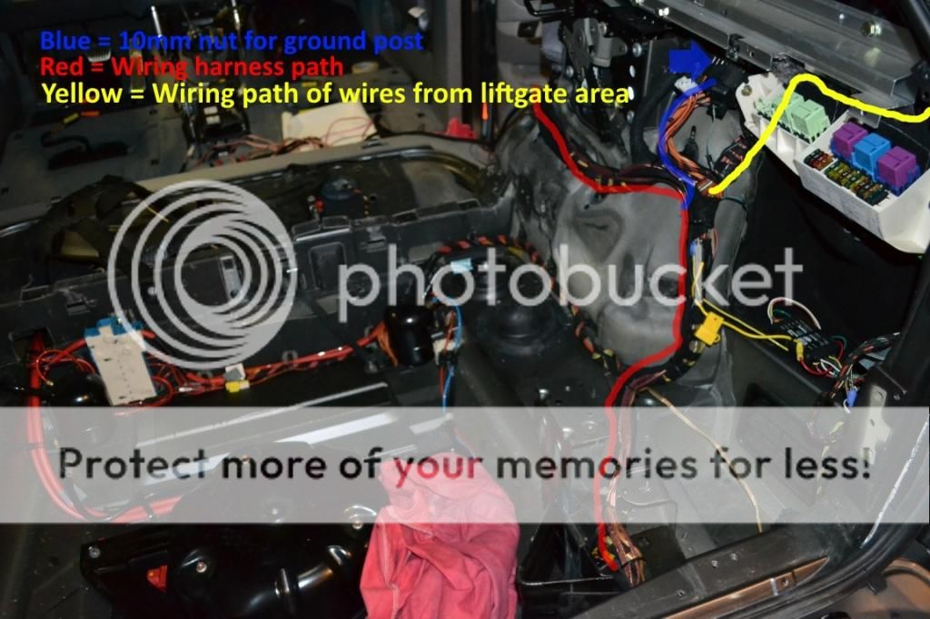
52. Connect your Fakra extension cable and antenna extension wire. Now run all your added wires out of module area following the factory harness. Secure your wiring along the factory harness every 6 inches or so as necessary. I ran my parking wire up the factory wiring to the fuse box area and soldered it with the camera ground to a ring terminal and installed on the ground post (10mm nut) in the fuse box area shown by the blue line after step 53.
53. Keep following the factory wiring up and over the wheel well area, behind the rear cushion bolster area, and down to where it disappears under the carpet. Keep all you wiring zip tied and neat so you won't have any problems reinstalling any trims or risk crimping/shorting a wire. Now you can go ahead and reinstall the rear trimming up to the rear seat backs in the reverse order they were removed. Don't install the battery cover bars or air pump yet. DO NOT connect negative battery terminal yet.
54. Remove the front and rear door sill trims. (3) Push pins for rear and (5) push pins for front door sills. Now remove the B pillar by pulling out door weather seals and prying from bottom first (4) push pins. You can now pull the carpet to expose factory wiring trays and covers.
55. Remove the plastic wire cover: (2) T20 plastic screws, (1) slotted plastic nut, and (1) 10mm plastic nut shown above. Route your wiring along the factory paths up until it splits and heads towards the center console. Follow the wiring towards the center console, not the front of the vehicle. There are wiring slits (shown below right) in the carpet you can utilize to pass the wires from under the carpet to around the center console. You can now reinstall the wire cover, B pillar, and door sills. You can also now install all of the interior up to the bottom seat cushion. Still, DO NOT connect the battery.
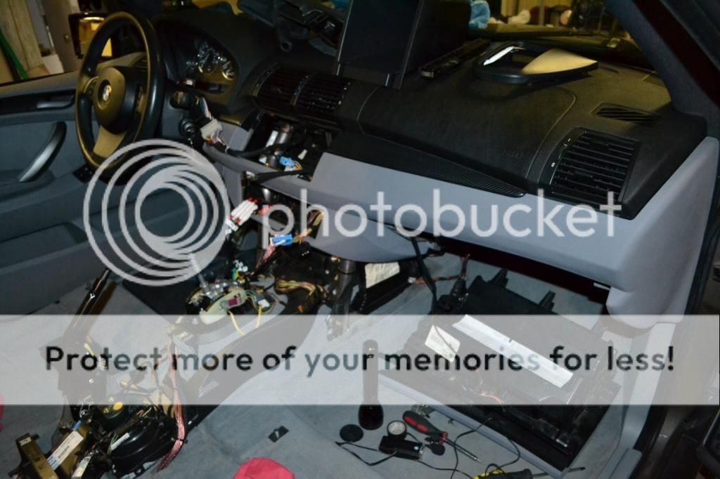
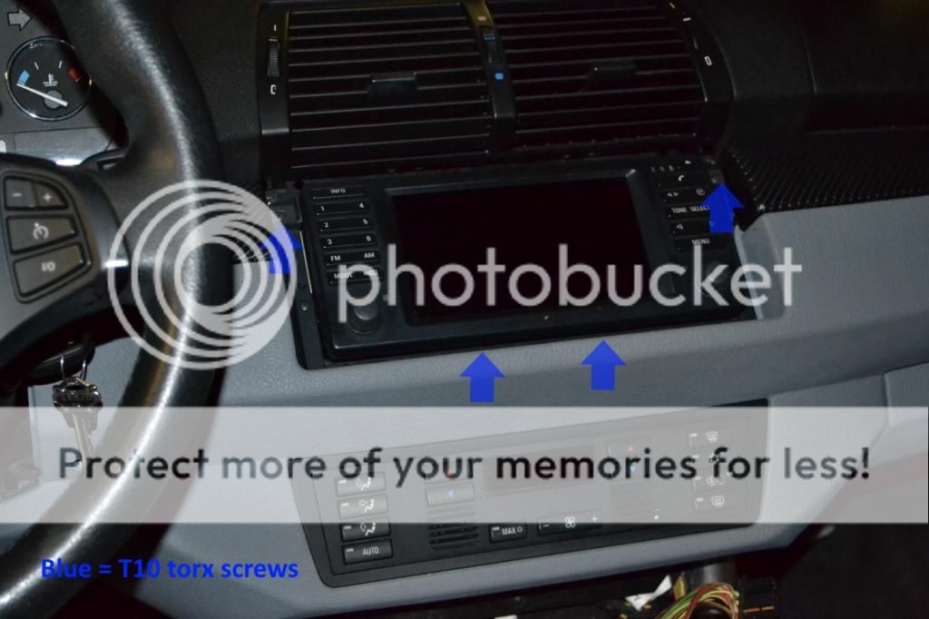
56. Remove the factory head unit now by prying the trim that goes around it with a panel tool. Then remove (4) T10 torx screws. Unplug/remove nav screen and push out the climate control console from behind. Unplug/remove climate controls to give you easy access to run wires up and into the radio area. You should have the Fakra cable, antenna cable, and backup cam video signal cable + trigger wire.

57. Now you can install the peripherals: USB/Ipod cable, Aux video/audio/USB cable (if installing), external mic (if installing), and GPS antenna. You may choose to put these things in different places than I, but this guide will show my locations. Drop the glove box (6) phillips screws. Two of these are "hidden" and can only be accessed after removing the pin holding the shock to the glove box and pulling the right side in to clear the stop. Looking from below you can now see the final two screws. You will probably have to remove the light inside the glove box as well before it will drop. Installing the aux video/USB cable in the rear lighter location simply involves removing the lighter and opening the hole up a bit to fit the new accessory.
58. I installed my USB/Ipod combo cable in the glove box which requires nothing special. Just route it out of the glove box and around the back to the radio area. Installing the GPS antenna and external mic requires pulling the A pillar. There is (1) T25 screw behind the SRS trim and (3) clips holding it in. Pull the door weather stripping and it will come out. Running the plugs down can be tricky but with patience can be accomplished. after getting the plugs down, routing them behind the glove box, and up into the stereo area. Now you can run the rest along the factory wires up the pillar. Important: Do this to keep them out of the way of the air bag.
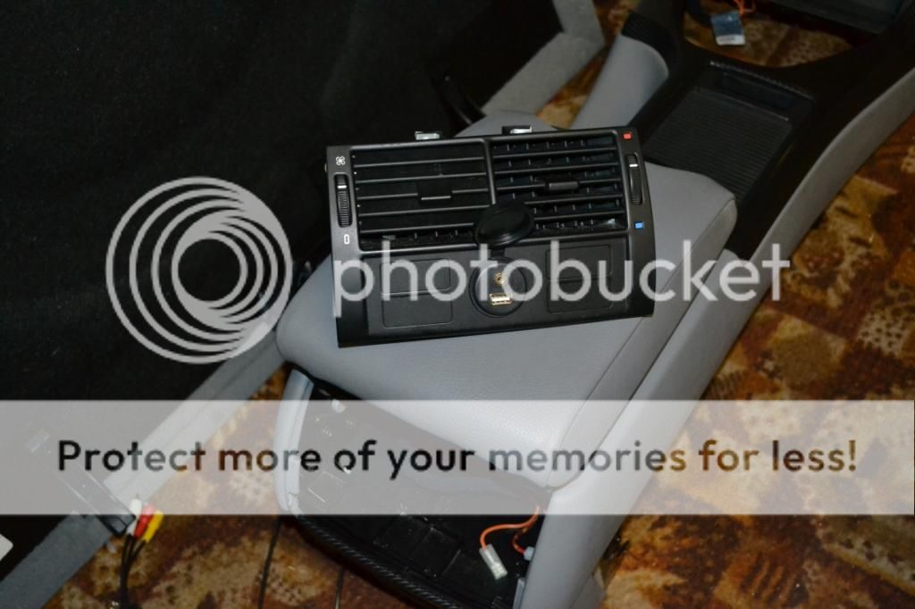
59. Go ahead and reinstall the glove box now as we won't need access back there again. You can also reinstall the center console now. If you chose this as an area for accessories, run the wires for them while installing the console. I installed an aux USB/video plug in the rear lighter location as pictured in step 57. Go ahead and install the front seats after the center console is fully installed. Almost looks like a complete vehicle again.
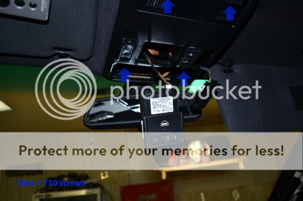
60. Remove the overhead vanity light console by popping the courtesy lights out with a plastic panel popper. Sometime the metal clips for these are bent in the front and get stuck. Just pull harder and it will come down so you can re-bend the clips to their proper shape. Pop out the homelink panel and then reach behind to remove the front console (mine is the ultrasonic alarm, yours may differ). Now drop the console itself after removing (4) T10 screws. Remove the factory microphone (if equipped) or grille so you can modify to fit the external mic.


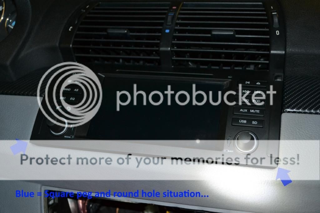
62. Reinstall the vanity mirror, upper console, pillar trim, and climate controls. Install is almost complete. In the blue plug that was attached to the factory nav there should be a Grey/Red wire that controls illumination. I cannot confirm this as I used the cig lighter Green/Red wire shown below. I learned about the Grey/Red wire after my installation was complete. It's certainly easier to get to than my solution which is why I am mentioning it here. Tap into one of those wires of your choosing for illumination control. Also notice my heat shrink on RCA connectors. I do this to prevent them from pulling out but is not necessary. Connect all of your other wires to the unit and slide it in as far as it will go... it won't fit, the bottom is square and not round like it needs to be. Don't get pissed and break something (like I was tempted to do)... we'll get back to that in a moment.

63. Finally, go to the cargo area, connect the battery, and reinstall all the associated pieces. Go ahead and put the cargo floor back in as well. We should be done back here. Now put your key in the ignition and test your unit on key pos 1. Note: upon starting the car the 4x4 warning light will illuminate. It will go out after driving a short distance. Your Avin unit should boot up. If you switch the lights on you should have illumination. Test that everything sounds good, radio, USB, etc. If all is good move on to the final step.
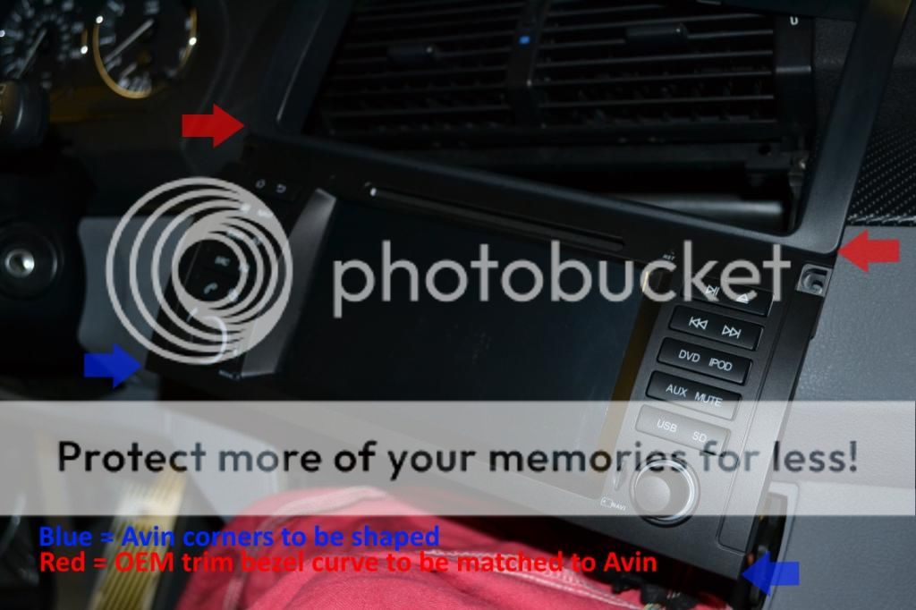
64. Now that we know everything works, grab your dremel or tool of choice for grinding. I used a small cone shaped grinding stone on my dremel for this. You have to reshape the Avin's lower corners to match the old trim that used to surround your nav unit. Go slow and remember you can always take more off, you can't add any back on. Just take your time and do a bunch of test fits. With a little work (took me 10 mins) you will have a nice radius on both sides and the unit should slide in nicely. It will be a snug fit... which is good in my book. You only need to secure it with the top (2) T10 screws from the original head unit. Before securing it permanently do a little wire management behind the radio with zip ties just to clean things up.

65. Crack open a beer, or 12 and start playing with your new head unit. If you made it this far congratulations, the picture below no longer scares you and you know your vehicle more intimately. If you are a non-factory navigation reader your life will be much simpler unless you are installing a reverse camera. Hopefully portions of this guide will still help you out as well. Feel free to drop me a line on www.xoutpost.com to user crystalworks if you have any questions.
 Conclusions/Final Thoughts
So far my wife and I absolutely love this unit. We have not had time to play with it fully yet though so I am reserving a full review until we've lived with it for at least a few months. Look for that in the future. This is a huge leap forward in terms of sheer technology (and enjoyment) for our X5 which we are hoping will last us a very long time. If I have to swap another motor into it I will... as I really enjoy driving it.
Is the unit "Plug and Play?" Maybe in the strictest sense of the phrase it is... but having to modify the front bezel to fit doesn't fit that definition to me. Also the reverse camera AvinUSA markets as for the E53 does not fit in any way shape or form. It is definitely NOT for this chassis. Other than those two gripes, which are very minor to me (I was a professional installer) the unit installed without much problem. It took a lot of time, but I went into it expecting that just because of the way I do installations. You could probably throw this thing in on a weekend if you install it like normal people.
Would I do it again? Absolutely. The quality of the unit seems good so far and the OEM looks are absolutely key to my wife and I. The screen looks beautiful and boasts a pretty impressive resolution. The external mic picked up conversations well and no one reports having a hard time hearing me. The UI and Android ecosystem are going to take some getting used to as a head unit. Not in a bad way, it's just very different than working with something on a traditional mobile electronics platform. The dual core processor seems to handle Kit Kat just fine with no real lag. I have not tried running a bunch of android apps at the same time though. Lastly, and possibly most importantly with a unit like this, Tommy seems to be VERY good with customer service and support. He has already sent me a software upgrade and answered tons of questions I had before purchasing. Support is key in my book and so far am very pleased. As I said, if you have any questions drop me a line on www.xoutpost.com as user crystalworks.
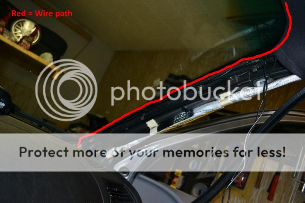
__________________
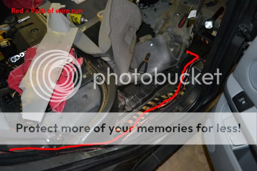
2005 X5 4.4i Build 04/05 Maintenance/Build Log
Nav, Pano, Sport (Purchased 06/14 w/ 109,000 miles) (Sold 8/15 w/121,000 miles)
2006 X5 4.8is Build 11/05 Maintenance/Build Log
Nav, DSP, Pano, Running Boards, OEM Tow Hitch, Cold Weather Pckg (Purchased 08/15 w/ 90,500 miles)
2010 X5 35d Build 02/10
Nav, HiFi, 6 DVD, Sports Pckg, Cold Weather Pckg, HUD, CAS, Running Boards, Leather Dash, PDC, Pano (Purchased 03/17 w/ 136,120 miles)
Last edited by crystalworks; 01-03-2015 at 02:02 PM.
|