Junction box
The junction box in the E70 plays a central role. In the junction box, the distribution box and junction box electronics form a unit. The junction box electronics is the central gateway in the vehicle.
Brief description of components
The junction box is located below the instrument panel in the passenger footwell. To reach the junction box, the cover below the instrument panel must be removed. After removing the mounting bolt on the junction box, the box can be folded down. This enables better access to the fuses and relays. The junction box consists of the distribution box and the junction box electronics.
Distribution box
The fuses and various firmly installed plug-in relays are located in the distribution box of the junction box. Depending on the vehicle equipment, the distribution box is fitted with different relays. The mounting for the junction box electronics is located in the junction box.
Junction Box Electronics
The junction box electronics are mechanically and electrically connected to the distribution box. The junction box electronics unit combines numerous functions in a single control unit. The junction box electronics unit is connected via a number of plug connections.
Graphic shows installation location in the E70
Index Explanation 1 Junction box
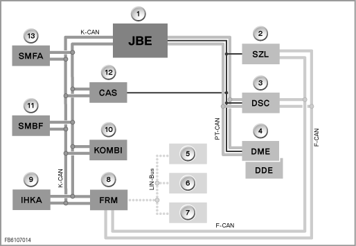
Block diagram for E70
Index Explanation Index Explanation 1 Junction Box Electronics 2 Steering column switch centre 3 Dynamic Stability Control 4 Engine control unit 5 Driver's exterior mirror (High) 6 Passenger's exterior mirror (High) 7 Door switching centre 8 Footwell module 9 Heater/air conditioning system 10 Instrument cluster 11 Seat module, front passenger 12 Car Access System 13 Seat module, driver
System functions
A number of functions are provided in the junction box electronics. The junction box electronics unit processes multiple signals, which it makes available to other bus subscribers on the electrical system. It also performs control tasks. Depending on the equipment variant, the following functions or signals can be processed by the junction box electronics:
- Gateway
- Power windows
- Wiper and washer system
- Central locking
- Seat heating
- Mirror heating and heated washer jets
- Bi-stable relay
- DSC button
Gateway
The junction box electronics enable a number of bus systems to communicate with one another. The junction box electronics unit provides the gateway function for the following bus systems:
Power windows
The junction box electronics control and monitor the power windows together with the footwell module.
Wiper and washer system
The junction box electronics unit detects the signals and makes them available to other equipment attached to the bus.
Central locking
The junction box electronics are the executing control unit for the central-locking system. The JBE handles activation of all the central-locking drives. The following control combinations are possible:
- Unlocking and deadlock release
Seat heating
The junction box electronics send a query to determine which seat module is installed. If the junction box electronics receive no check-back signal, it handles activation of the seat heating. The junction box electronics generate a pulse-modulated signal to activate the seat heating. If a seat module is fitted, the seat heating is activated directly by the seat module.
Mirror heating and heated washer jets
The junction box electronics control the mirror heating and heated washer jets.
Bi-stable relay
The bi-stable relay is used to shut down terminal 30g-f if there is a closed-circuit current fault.
Functions for instrument cluster
The junction box electronics unit detects the signals for the instrument cluster.
DSC button
The junction box electronics detect signals from the DSC button.
Other tasks of the junction box electronics
- Line connection
As well as its electronic function, the junction box electronics unit (JBE) also has a connector function. A great many cables connected to the junction box electronics are interconnected.
- Relay
The junction box electronics have internal and external relays. The excitation coils on all relays are permanently supplied through the positive cable. The positive cable of the external relay lies on the load circuit to be switched through. The positive cable of the internal relay lies on the secured supply cable of the junction box electronics. All relays are controlled via the negative lead. All internal relays and the relay for wiper stage 1 and wiper stage 2 are located downstream of each fuse on the current circuit. All other external relays lie in the current circuit before the fuse.
Internal relays are:- Relay for the rear power window drives
- Relay for the central-locking system
The external relays are:
- Relay for drive, rear window wiper
- Relay for wiper stage 1 and wiper stage 2 drives
- Relay for headlight cleaning
- Relay for heated rear window
- Bistable relay (deactivation of closed-circuit current fault)
You should try to find the TIS.... also the JBE connects to the FRM (aka footwell module or Foot Rest Module)....