I tried to connect the Ice>Link harness to the 3 and 6 pin CD changer connectors in my 2006 X5, but with the analog 6 pin connection, there was no sound. I was one of the few people with an X5 that required the digital connection to my amplifier. Tom helped me get the right parts, but I quickly saw a tidier way to hook things up.
Here is my modification of the Ice>Link cable that reduces the number of connections and simplifies installation in DSP equipped (required) cars.
Picture 1: The original cable supplied by Tom.
 Picture 2:
 Close up of the 3 and 6 pin connectors. 3 pin is data and power, while 6 pin is analog audio. There is an in-line fuse on the brown (+12V).
 Picture 3:
 Better view of the 6 pin analog audio connector. Black jumper bridges ground for both left and right channels.
 Picture 4:
 Cut off the 6 pin connector. This will be discarded.
 Picture 5:
 Strip of the outer insulation from the twin coaxial analog audio cables.
 Picture 6:
 Twist the shield wires into leads. These are the negatives for the analog audio.
 Picture 7:
 Tin the leads. I used a silver based solder.
 Picture 8:
 Put short lengths of heat shrink tubing over the existing wire insulation. This builds the cables diameter making better anchor points for the RCA connectors.
 Picture 9:
 Some good quality, inexpensive Neutrik RCA connectors.
 Picture 10:
 Solder on the RCAs. Don't forget to put the RCA barrels over wire before soldering.
 Picture 11:
 Finished twin RCA connectors in place of single 6 pin BMW proprietary connector.
 Picture 12:
 Carefully remove black wire from power 3 pin connector to solder negative wire of DSP power cable. Reinsert pin into connector when done soldering.
 Picture 13:
 Solder positive (black with white strip) cable to brown wire fuse terminal (after the fuse). Reinsert the fuse terminal pin when finished.
 Picture 14:
 Bundle the wires together.
 Picture 15:
 Behold the finished cable.
 Picture 16:
 All finished. Power for DSP module is pulled from CD changer power, and it's fused.
 Picture 17:
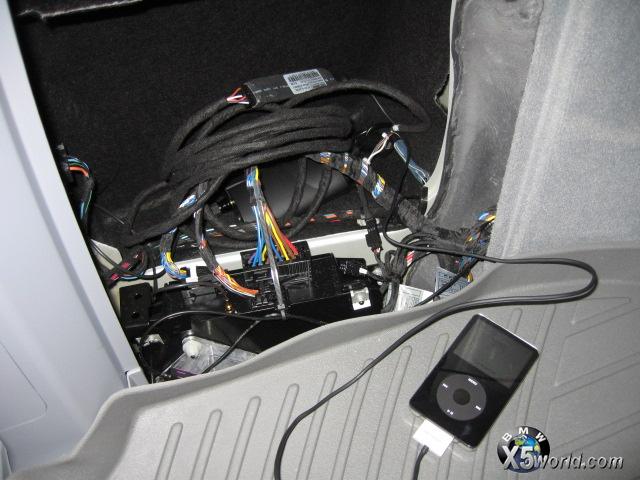
 Harness connects to the vehicle at two points: 3 pin power/data connector and coaxial digital audio connector on amplifier.
 Picture 18:
 Test the system with your iPod in the boot.
Next challenge is getting the cable routed to the center console.