
|
|
|
|
||||||||||
| Xoutpost server transfer and maintenance is occurring.... |
| Xoutpost is currently undergoing a planned server migration.... stay tuned for new developments.... sincerely, the management |
 |
|
|
LinkBack | Thread Tools | Display Modes |
|
#1
 07-17-2012, 05:56 PM
|
|||
|
|||
|
ULF cant Pair, Red light and ACTIVATE PHONE
After having read waaaaay to follow instructions and do not get to know what happens to my car bluetooth, something happens ... Then buy an X5 and not get it to work the bluetooth, the car comes standard with bluetooth, browser MK3, a TV and the DSP, there is no way to work the bluetooth. Upon entering the telephone always puts ACTIVATE PHONE red and the middle light of the three screen is always on, I can not pair the phone or by pressing the pairing button on the center console or by mass mating pin connector ULF. I tried another and ULF is the same. According to the pinout you put into the forum with 12 cables mounted bluetooth because my 54-pin connector is about 30 cables. I stamped the cables and there are some who do not reach Indicate to the ULF to BM54, and others go but to another pin. I commented: +12 V Directo------------------PIN 17 ULF -----> 15 X18126 OK MASA o GND-------------------PIN 36 ULF -----> 12 X18126 OK +12 V Contacto----------------PIN 35 ULF -----> 16 X18126 OK MIC + -------------------------PIN 1 ULF -----> MIC OK MIC ------------------------ PIN 19 ULF -----> MIC OK MIC Shield --------------------PIN 21 ULF -----> MIC OK I-BUS ------------------------PIN 15 ULF ------> 14 X18126 ERR (connect to 9) Audio Tel + -------------------PIN 37 ULF -----> 6 X13649 ERR (no cable) Audio Tel -------------------PIN 38 ULF -----> 12 X13649 ERR (no cable) TEL ON -----------------------PIN 33 ULF -----> 11 X18126 ERR (no cable) MUTE ------------------------PIN 51 ULF -----> 10 X18126 Pairing ------------------PIN 32 ULF -----> OK If I remove the connector from the ULF, and leave the car without hands-free all works as it is logical and can not access the phone, if I connect the red light comes on and get the same message. When removing the ULF I have found there is a four-wire hose that is cut and not going anywhere. If I try to make a new connector according to your diagrams I find I have some pins that I need that are engaged in the BM54. Now in photos: My connector ULF  The ULF connector with the four loose wires.  My connector BM54  General view  Plugged with ULF (red, ACTIVE PHONE, not match)  Message in telphone screen  ULF Disconnected  Center console and matching button. I removed the console and all cables are properly connected.  See if someone tells me it can happen. I've thought of everything, the car had a back beat and montasen incompatible wiring, or instead of ULF montase the other phone there (though I think that does not have bluetooth) and a ULF montasen break. .. No, I do not block anything. CAN SOMEONE HELP ME? Thanks in advance. 
|
| Sponsored Links | |
|
|
|
|
#2
08-16-2012, 06:57 AM
|
||||
|
||||
|
You have several problems.
This: 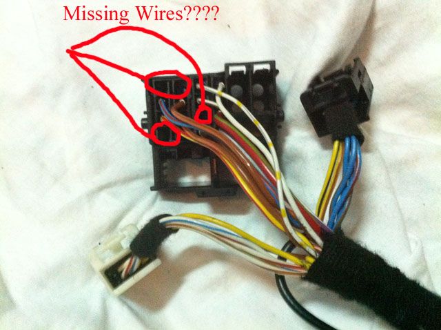 And this: 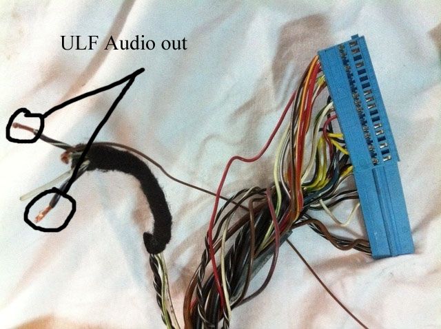 from the look of the 54pin plug, you car was wired for BITII or TCU *****NOT**** BT, you need to start again and sort the wires out. This is a **FULL** list of the pins for the ULF. 1 - Microphone - Positive Input signal 19- Microphone - Negative input signal 21- Microphone - Shield 11- Eject box - Cradle on 22- Eject box - +12v 32- Eject box - Pair 39- Eject box - Gnd 34- Telephone ON signal [Compensator] [signal amp power] 36- Ground [Ground splice] [Slpice to pin 12] 15- I-bus signal line [Input to radio, pin 9 of x13646 quadloc] 17- Terminal 30 voltage supply [Fuse F57] [+12v Battery] [Slpice to pin 15 of x13646 quadloc] 33- Telephone ON signal [Input to radio, pin 11 of x13646 quadloc] {{ if you have OEM DSP, send to DSP instead}} 35- Voltage supply terminal R [K3 Unloader relay, terminal R] [+12v Ignition] [Slpice to pin 16 of x13646 quadloc] 36- Ground [Ground splice] [Slpice to pin 12 of x13646 quadloc] 51- Telephone mute signal [Slpice to pin 10 of x13646 quadloc] {{ if you have OEM DSP, send to DSP instead}} 37- Front loudspeaker + [Voice input to radio, pin 6 of X13649 12pin block] {{ if you have OEM DSP, send to DSP instead}} 38- Front loudspeaker - [Voice input to radio, pin 12 of X13649 12pin block] {{ if you have OEM DSP, send to DSP instead}} 52- Nighttime illumination signal [Terminal 58g splice] Also you have OEM DSP so this makes thing more difficult, and you will need to check the wires to the DSP amp. The pinouts for the DSP 18 pin connector are: 2- Audio in from ULF negative (-) signal - ULF pin 38 11 Audio in from ULF Positive (+) signal - ULF pin 37 13-Telephone mute signal - ULF pin 51 15-Telephone ON signal - ULF pin 33
__________________
Sept 03, M3, Silver Grey. Retro-fits: Modded Mk4 DVD Drive, OEM Bluetooth, VR Control, Rainbow Speaker Upgrade, Sony SOT Amp, HK Sub, CCFL, Intravee II, NightMode.
|
|
| Bookmarks |
|
|
|
|


 Linear Mode


