
|
|
|
|
||||||||||
| Xoutpost server transfer and maintenance is occurring.... |
| Xoutpost is currently undergoing a planned server migration.... stay tuned for new developments.... sincerely, the management |
|
|
LinkBack | Thread Tools | Display Modes |
|
#1
 03-03-2010, 02:24 PM
|
|||
|
|||
|
Easier CVJ Boot Replacement
I needed to replace the CVJ boots on my wife's 325XI, but was alarmed by the amount of work and special tools to do the job. I decided to make my own special tool to do the repair myself. here's a pictoral of what I made in all it's glory:
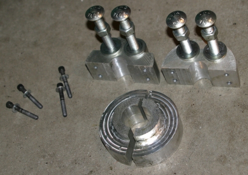 It's made out of aluminum, because I could band saw it, and because you can run aluminum past a router if you mount a 1/4" end mill in it. I used some stuff called Nikx Stikx to lube the mill, but it still dulls after a while because of the speed of the router. You can see some of the milling marks where I spun the tool. Here's the tool mounted to a piece of aluminum tubing that represents the axle. 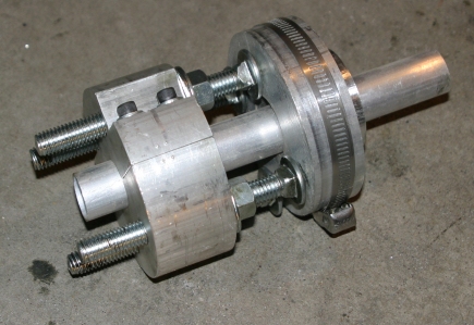  This is way overbuilt, but I had read so much about how tough the joint comes apart (a BMW tech told me that it was almost a press fit) that I made sure the tool would do the job. If I made it again, I would just have slotted the pusher rather than use a band clamp to hold two pieces together. The pressure needed is nowhere near this level of construction. The carriage bolts are 1/2". Seriously, 5/16" or 3/8" would be sufficient, and only two are really needed. Note that I made an extension on the pusher part, so that the tool pushed on the CVJ itself, and not the housing. It's hard to get the axle to line up square with the CVJ housing, but with the extension it doesn't matter. I bought two other tools to make the repair simpler. A boot clamp squeezer: 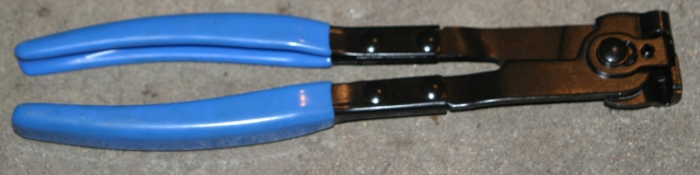 And a ball joint separator: 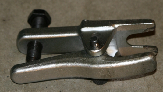 I didn't like this particular ball joint separator. It was too bulky to fit well between the CVJ housing and the top of the ball joint nut. Hard to see, but here's a closeup without the tool. 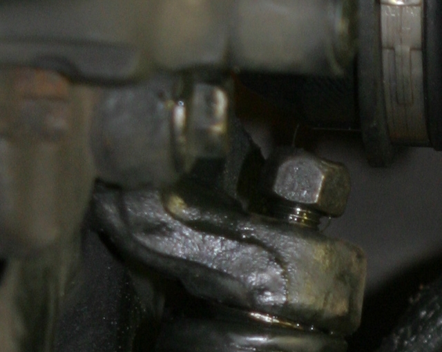 Not much space there. Look at how precariously it is caught on the edge of the nut in the picture below. I have the nut on far enough so that the bolt is just level with the top of the nut. Not sure what's a better make. I got it to work, but there have to be better units out there. Here's the repair: 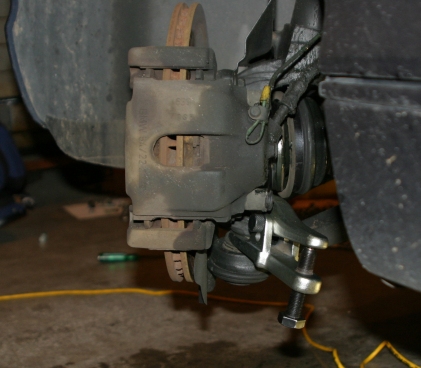 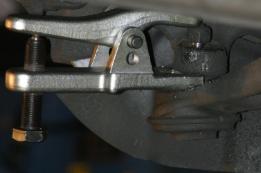 Wheel off, I pop the swing-arm. This is the only nut that I removed from the car during the entire repair. Note that I left the nut on the top so that when it popped, it didn't fly around. Once you've popped the swing arm, you can move the outboard axle assembly around pretty easily so be careful not to pull on the brake line or the wire to the wheel speed sensor. There's also a leveler under here that senses level for the headlights. Use care. Tool in use: 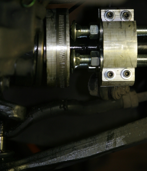 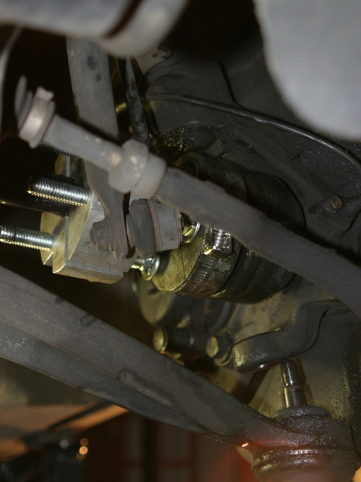 I alternated between two of the bolts, using a wrench on the flats of the carriage bolt and the nut to push the joint apart. Once the Cir-Clip popped, I could just use one of the carriage bolts to push the joint apart the rest of the way. Again, once the cir-clip popped, I was pleasantly surprised that this joint was not hard to pull apart. I probably could have used a pry-bar to speed up the process, but I wanted to take it slow and controlled, so I just used the carriage bolts to slowly pull the axle from the joint I'll spare you pictures of the gritty details of cleaning the joint, but I disassembled it, cleaned everything thoroughly and reassembled it. Here's the joint ready for re-greasing and reassembly. I squeezed the entire tube into the center of the joint, and worked it back and forth until grease squeezed out between all the bearings. That's the new cir-clip on the drive shaft. 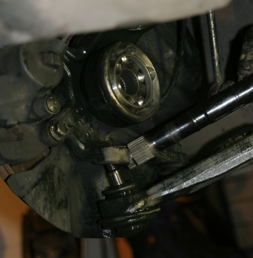 A little explanation is in order for the reassembly jig here. I originally made this turnbuckle tool, thinking that I could do both the dis-assembly and reassembly with this simple jig. It turned out that I could not get near enough pushing pressure to pop the cir-clip with the turnbuckle, it just folded in half. But a turnbuckle is really made to pull. Here I used it to draw the joint together. It's loosely bolted through the ball joint connection. 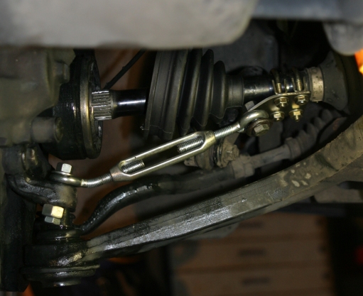 Note that my plan was to just put a threaded bolt hole into the aluminum axle clamp that I made, bolt the turnbuckle to it and pull with that. But I had this little jig handy and just lying there all sad from it's previous failure, so I gave it a job. You can easily draw the axle into the CVJ by turning the turnbuckle by hand for about 3/4 of the way. To start, pull the axle in up to the cir-clip, then put a very slight amount of pull on it as you push the cir-clip in with a flat screwdriver. If you can't turn the turnbuckle by hand, your cir-clip is not seated and you are binding on it. Make sure the open side of the cir-clip is pointing toward the floor. Easier to get to that way. Draw it in. Sooner or later you will need more purchase than just your hand. I used a small wrench slid through the slot of the turnbuckle. When you are getting close, be quiet and you can hear the cir-clip snap home. It's faint. Turning more on the turnbuckle brings up resistance, letting you know that you are there. Put the swing arm back in place. I used a jack stand, and let the car down slowly onto the swing-arm. This puts pressure on the ball joint to keep it from turning as you tighten it. Don't let the full weight of the car down on your swingarm, you might bend it. 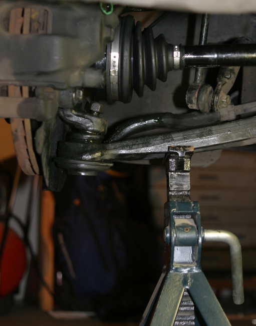 About this time, I was 3 hours into the project, both wheels were on the car and I was done. I don't really know the rest of you reading this, but I strongly recommend popping a beer at this point, leaning back against the back door step, and basking in the limelight for a moment. Your wife will be along soon to remind you to clean the garage floor and that she's conveniently written a reminder of the next project looming up for you on her little whiteboard in the kitchen. The new tool sits in my cabinet, if anyone wants to borrow it. I also did drawings so I could have this thing laser cut cheaply if someone wants their own. If so, there are a number of improvements that I'd make. The split collar would be one-piece with a slot to drop over the axle. The split axle clamp would have swing bolts with nuts to put it together (it was a headache lining it up under the car) and it would have a square shape rather than a fitted circular shape for where it contacts the axle, so different axle diameters could be accommodated. I spoke with a garage mechanic, and he said that built this way, this tool would work with 85-90% of the cars made. If you would like one of these for your very own, contact me and I'll check out how much it would cost. (no one's asked yet, so I haven't checked.) Gotta go. The under-cabinet lights in the kitchen need fixing, but that's for another post. DIY Dave |
| Bookmarks |
|
|
|
|


 Threaded Mode

