|
Xoutpost server transfer and maintenance is occurring.... |
Xoutpost is currently undergoing a planned server migration.... stay tuned for new developments.... sincerely, the management |
|
LinkBack | Thread Tools | Display Modes |
#131
|
||||
|
||||
thanks |
Sponsored Links | |
|
#132
|
|||
|
|||
Yes, this is the exact one i purchased
BMW 3 5 Series x5 x6 Backup Rear View Camera Monitor | eBay i tested the camera out on my tv, great quality for a CMOS camera. has the lines aswell. |
#133
|
|||
|
|||
Hi,
my camera arrived. Is the CCD Sony Car Rear View Camera for BMW 1 3 5 6 Series x3 x5 x6 E39 E53 E82 M3 E46 | eBay, which i will install this weekend. Now to the question: Where shall the video output from the camera be plugged? My E53 has the PDC (front and rear), OBD 16:9, and video module (analog TV tuner). As i understood, i will connect: pin 86 from relay to reverse light positive pin 85 and 87 from relay jumped to reverse light ground pin 30 from relay to pin 17 of the blue plug of video module. Is this right? Best regards, Paulo
__________________
BMW E53 4.8 IS 2006 - |
#134
|
||||
|
||||
pw, i suspect that this particular camera will not fit into the license plate opening... before wasting your weekend, pop the license plate light cover and see if it will or not... if it fits, I want to see the pictures... If it doesn't fit, then... maybe a bumble bee camera?
there are schematics of the connections from the camera to the TV module and the trigger wire in this thread - camera needs power, the video feed from camera goes to TV module, and the trigger wire needs ground to send the video signal to the front of the car. you should not use the reverse light circuitry as the voltage there is NOT steady 12V but rather a pulse modulated wave, which will result in front image flickering. Since you have the factory PDC, you may consider using the Pin 7 from the center plug of the PDC to get a (+) signal to a SMALLER relay (see this very thread for the part number and the specs), which will apply (-) to the trigger wire. One thing at a time... check the camera fitment first... then post your progress, we will guide you further... |
#135
|
|||
|
|||
TerminarorX5,
thx for your hint. The camera does not fit, not because of it's size, but because the inside of the trim which holds the opening button and the license plate lights are a unique piece, with a circuit board inside, so, it's not possible to remove the bulb holder, only the transparent plastic window, which i discover, has part of the tabs broken. So, i'm considering the following: Getting the other camera i have (Car Rear View Reverse Camera for BMW 1 3 5 6 7 Series x3 x5 x6 All BMW | eBay), cutting the cable from the camera to the splitter, make it fit to the lights and push button connector, make mini three pin connector and connect it to the splitter, which will be inside the rear door. As these cable is not shielded, i think it will not pose a problem. After done, i will pots the pictures, so to go further. Best regards and thx again for the hint. Spared me time Paulo
__________________
BMW E53 4.8 IS 2006 - Last edited by pw44; 10-27-2012 at 09:36 AM. |
#136
|
||||
|
||||
Well folks, you know that I had bought that camera off eBay that is advertized as one for E53... The back of the camera is too fat and will not fit into the opening of the license plate light, as the light assembly has only the lid that comes off, and not a "box" with the light bulb, like in E39 or the others... I let the eBay seller know but they continue selling that camera to E53 drivers as evidenced by the number of people who are trying to use it.
I have decided that it is better to modify/break a $20 chinese camera off ebay to suit the car than to modify a $150 piece of $75K German car to suit the cheap camera. I have taken a utility knife and gently cut out the cover of the camera to open it up... There are two screws that need to come off - on mine, they broke off the base but it did not affect the usability of the camera. also, please note that the dimensions of the OE cover and the camera housing are different, the camera housing is slightly wider and shorter than the OE cover. since the camera cable will not fit through the opening of the OE plug, I cut the cable - now it will fit with no questions. the camera will fit into the opening with a slight push - the inner side of the trunk handle is more plyable than the outer, body colored shiny part - you can see how the inner part is buldging... But since the camera housing is shorter, it leaves the opening holes wide open to the elements - hence I got the liquid rubber in hopes to insulate the holes and cover up the open circuit board of the camera, and also I used the rubber to attach the LED for the license plate... at one point I was thinking about keeping the original light bulb inside and get whatever light will get through the little window but I think that the heat generated by incandecsent light bulb will be to much for the camera to tolerate... Here are the pictures - i don't really know how to stick the text in between the pics... one day I will learn... Since I can stick only 12 pics at a time - check the following post for more... |
#137
|
||||
|
||||
the camera sits kind of ok in the opening - I did not secure it by any means other than the natural tension applied by the smaller opening to the wider body. Also, I used generous amounts of the rubber sealant inside that might do some sticking...
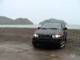
It looks better on the car than the bumble bee camera did on my 4.6iS... Since this particular setup is NON functional yet, I can not tell you if the angle of the view is any good or not - the bumble bee camera was fully adjustable, as I could turn it around its axis and bend the metal bracket for a better view... Two last pictures are of the installed product: the one with Virginia license plate has the license plate light camera (not operational yet) and the one with the Pennsylvania license plate has a functional bumble bee camera that I had used since 2007... Once I connect this camera to the power and the video system, I will be able to report further... |
#138
|
||||
|
||||
Next step is to obtain the power on ignition for the camera (another option is to power the camera once reverse gear is engaged) and obtain power for the left license plate light.
Power for the license plate light comes from the original source of that power from connector X1739. This connector has 4 wires 1 left license plate light 2 trunk lid release button 3 ground (brown wire) 4 right license plate light (also feeds trailer module for parking lights for trailer) In ideal situation I would have a small, 3 harness made for the male and female part of the connector where the pin 1 and 3 would have been tapped for the LED lights. Unfortunately, some of these connectors almost impossible to source thus I resorted to the soldering the taps. Since the tap is T, I could not use shrink wrap, so it was isolated by regular tape. The draw on the circuit by the LEDs is much less than regular lamp, so we are ok here. Nevertheless, the LEDs do set off the Check Licplate Light warning. This issue can be later rectified by the programming of the car. Now would be a good time to restore the cut wiring for the camera good thing is, the wires are colored, so there is no way to make a mistake. In this case I used the shrink wrap and the tape. It is time to find a good source of power on ignition. After studying the schematics from the WDS, a connector X13057 from the rear wiper was identified. Pin 1 was ground (brown wire) and pin 13 is the power on ignition lead (red wire with black stripe). The power lead for this camera has come integrated with a wireless video transmitter I was not sure how well the wireless transmission will work but decided to give it a try before running cables all the way from the trunk lid to the bottom of the battery compartment. I tapped the power to the wireless module and connected the power and the video cable to the camera. Before zipping everything, I tested the reception using the wireless receiver and a portable test monitor. The monitor had its own battery compartment, and I used a 9V battery to power up the wireless receiver. The reception was good next to the transmitter, so I walked around and actually went inside the house the reception was excellent. Now would be a good time to zip everything up and start wiring up the receiver to the TV module. To be continued... |
#139
|
||||
|
||||
Why didn't I think of that? I modified the $150 part. Still didn't work but I managed to solder and silicone the circuit board back in to put it back to "normal"
__________________
2004 E53 4.4L N62 |
#140
|
||||
|
||||
you still should be able to take the cheap way out - i can try to help you...
|
Bookmarks |
Thread Tools | |
Display Modes | |
|
|
|