
|
|
|
|
||||||||||
| Xoutpost server transfer and maintenance is occurring.... |
| Xoutpost is currently undergoing a planned server migration.... stay tuned for new developments.... sincerely, the management |
 |
|
|
LinkBack | Thread Tools | Display Modes |
|
#31
 09-05-2012, 01:09 PM
|
||||
|
||||
|
__________________
2003 530i, Silver on Grey, BC Coilovers, Square 9.5" M-Parallels, Gloss Black Roof 2007 328i, Alpine White on Black, Sport/Nav/Premium SOLD: 2006 X5 4.8is, Lemans Blue on Black 
|
| Sponsored Links | |
|
|
|
|
#32
09-05-2012, 01:15 PM
|
||||
|
||||
|
Quote:
Anyone else can answer definitively?
|
|
#33
09-05-2012, 01:16 PM
|
||||
|
||||
|
Hey Jose, wassup???.
I haven't seen this post before, but i am wondering about your schematics... You are connecting the (+) from the AE LED bulb to the (+) from the ignition directly - essentially, you are connecting a balanced, monitored line from the LCM to the Ignition Hot wire from somewhere else... I have read the entire post, and I think some of the issues that you were having stemmed from the fact that you had two power sources on a single line - basically a single wire going directly from LCM to Terminal 15 (i think terminal 15 is considered ignition hot, right? or, is it T-30?) regardless, you have two sources of (+) juice going to a same wire and having only one return, the (-) wire at the LED. This setup may raise issues, as the LCM line is balanced, meaning that the current flow and the resistance of the line is measured and anything that is off the balance, will throw a flag... To avoid issues, you might want to add diodes to the lines, to prevent a back flow LCM<----------->LED<-----------> T-15 with a (-) wire at the LED vs LCM-->--diode--->LED<----diode--<- T-15 with a (-) wire at the LED Or, take the (+) directly from the battery and isolate it with a relay but you still might have a backflow of current into the LCM... I am in the same boat, I would like to run the original factory AEs as the DRL, when the ignition is on, I want them to be on... I tried to accomplish that via programming, as supposedly there is some coding that allows that to happen, but I was not able to do that... Last resort, is doing a hardwire... What do you think about hat diode setup? Any one else can chip in?
__________________
E53 X5 4.6iS 147K mi - Sold May 2013 Tireprints left in: USA, Nicaragua, Costa Rica, Panama, Russia  E53 X5 4.8iS built 2005-10-17 66200 mi - June 2012 96000 mi - June 2013 112000 mi - June 2014 OEM fire extinguisher OE first aid kit OE tow hitch OE TV module OE aspheric mirror K&N air filter black/white badges rear camera 4-channel video recorder Here is the list of things I have done to the X
|
|
#34
09-05-2012, 01:26 PM
|
||||
|
||||
|
Okay a few clarifications here is neeeded.
I have rewired my angel eyes and its power source so many different ways in the past. Here's the story. First I had the power source at the footwell inside the cabin. Then I tapped a green ignition wire at the steering column. I had it there for a long time. I have NEVER wired it to the LCM. Then recently, all of a sudden, my angel eyes did not work with the key on BUT it did when the parking or headlights were on. I got the check side light message even though the AE bulbs are okay. Then TOM pointed out that my power source (the green ignition wire) was probably disconnected. That's why my angel eyes worked normally - because it was still wired to the stock harness like normal and getting power when the light switch is on but NOT when the key is on. So, I just recently used the ECU key-on power source. I have no problems right now as far as the check side light message. All the problems previously was from previous iteratiosn of my wiring. I have ZERO problems currently but maybe something will pop-up later. So, now tell me. Others have used similar power sources whether it be the ECU, lCM or accessory wire. What's the difference here? Why would those methods work and not this way? Am I missing a relay or something else?
|
|
#35
09-05-2012, 01:27 PM
|
||||
|
||||
|
The voltage in the 12 volts system of a car will not double, as no matter how you will connect wires in that car, the voltage will still be 12 volts, unless you are using the step increasers, that specifically designed to increase the voltage... However, you can introduce currents into a line that will interfere with the operation of the line, and interfere with semiconductors that are part of the electronic modules, and you may introduce a full 12 V into a line that has a resticted, 5V or 9V or whatever other voltage level, and thus disrupt the intended operation...
that what might have happened in this case... we want the AEs to operate either when the ignition is turned on, and the LCM has the AE line "sleeping", and not cold checking for balance, or to operate when the lights are on, and the LCM thinks that the AEs operate from the juice supplied by the LCM... The whole line testing, when cold or hot, can be turned off via programming, thus eliminating those flickers, when the lines to AEs are tested...
|
|
#36
09-05-2012, 01:33 PM
|
||||
|
||||
|
Quote:
I don't think I can turn off that check with the GT1 but I read a post you can do it with another system - forgot which one (INPA?). So, at least I can't over volt this way. But what you're saying is the check side light message may come back.
|
|
#37
09-05-2012, 01:35 PM
|
||||
|
||||
|
Quote:
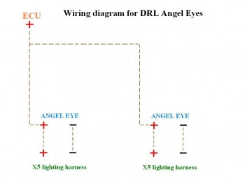
If this diagram still stands true to some extend, the (+) going from the ECU into the (+) from the angel eyes, effectively connects the (+) from the ECU via the (+) from the AE right to the (+) of the LCM - where does the (+) for the AE come from?... I am not an electrical engineer, I am just an electrionics' technician... but it has been from my old college days: when you have a connection point on the wires, it is irrelevant, where the connection point is located physically, as essentially, that point can be anywhere on the lenghth of the wire - still deemed as same... (+) from ECU -----> (+) from AE ---->(+) from LCM equals (+) from ECU ---> (+) from LCM --- > (+) from AE
|
|
#38
09-05-2012, 01:37 PM
|
||||
|
||||
|
i used the NCS Expert to turn off cold monitoring of the AEs
|
|
#39
09-05-2012, 01:41 PM
|
||||
|
||||
|
but like you said, the cold or hot monitoring is not the principal issue... main thing is - not to fry something... that is why we should electrically isolate the modules.. as long as the solution doesn't require hauling a trailer full of electronic components!!! lol...

|
|
#40
09-05-2012, 01:41 PM
|
||||
|
||||
|
Quote:
 Read the alternate wiring method in Step I. That's the simplest explanation. Basically leave the wiring exactly like stock. Just add an extra wire that taps the original harness AE positive wire that then goes to the ECU. That's it. 
|
|
| Bookmarks |
|
|
|
|








 Linear Mode


