
|
|
|
|
||||||||||
| Xoutpost server transfer and maintenance is occurring.... |
| Xoutpost is currently undergoing a planned server migration.... stay tuned for new developments.... sincerely, the management |
|
|
LinkBack | Thread Tools | Display Modes |
|
#1
 08-27-2014, 12:51 PM
|
|||
|
|||
|
Valve stem seals, coolant pipe & coolant hoses replaced - some pointers
I finished changing the valve stem seals, the coolant pipe and while in there, I also changed all the cooling related hoses.
I won't be doing a DIY, I will just make some pointers touching on some very good DIY's and youtube vids, which aren't specifically for the e53 N62. If anyone wants to tackle the job, here are the parts you will need: If doing the coolant pipe: O-ring coolant pipe p/n 11531710048 (x1) Valley pan cap seal p/n 11147507278 (x1) Return pipe p/n 11511439976 (x1) Intake manifold steel gasket p/n 11617521181 (x2) Throttle body O-ring p/n 13547510433 (x1) Your choice of coolant pipe - I opted for the more expensive AGA pipe, which has Viton O-rings, as opposed to the cheaper options, which don't (and will probably fail as well). If doing the valve stem seals: Throttle body O-ring p/n 13547510433 (x1) - not necessary to buy twice if doing both jobs Right upper timing case seal p/n 11147506424 (x1) Left upper timing case seal p/n 11147506425 (x1) Solenoid big O-ring p/n 11367513222 (x4) Solenoid small O-ring p/n 11367546379 (x4) Vacuum pump O-ring p/n 11667509080 (x1) Valve cover seal right p/n 11127513194 (x1) Valve cover seal left p/n 11127513195 (x1) Repair kit valve stem seal p/n 11340029751 (x2) Eccentric shaft sensor seal p/n 11127518420 (x2) Camshaft positioning sensor O-ring p/n 12141748398 (x4) Valvetronic O-ring p/n 07119903596 (x2) Optional: Valvetronic spacer torx bolt p/n07129900465 (x2) I also purchased all the cooling hoses, including the rear ones from the firewall to heater valve, firewall to coolant pipe rear, and from heater valve to auxiliary pump. Plus all the front hoses. To tackle both jobs, I started by removing the intake manifold using this awesome DIY, which is for a 6 series, so there are a few things we don't have to do, and some others we have to. We don't have to remove the braces (we don't have them), we don't have to take the big wiring cable from the ECU box. Also, removal of the air box, microfilter housing etc is a bit different, but this is a very easy and straightforward job. However, you want to remove the cables form the battery, because you will need to remove the positive cable from under the hood. Here is how it looked just before removing the wiring harness around the intake manifold: 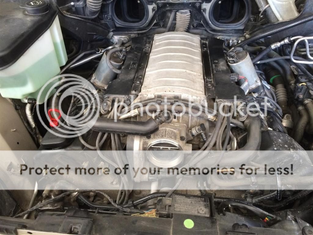 Here is the old pipe cut:  And here is the AGA expandable pipe installed: 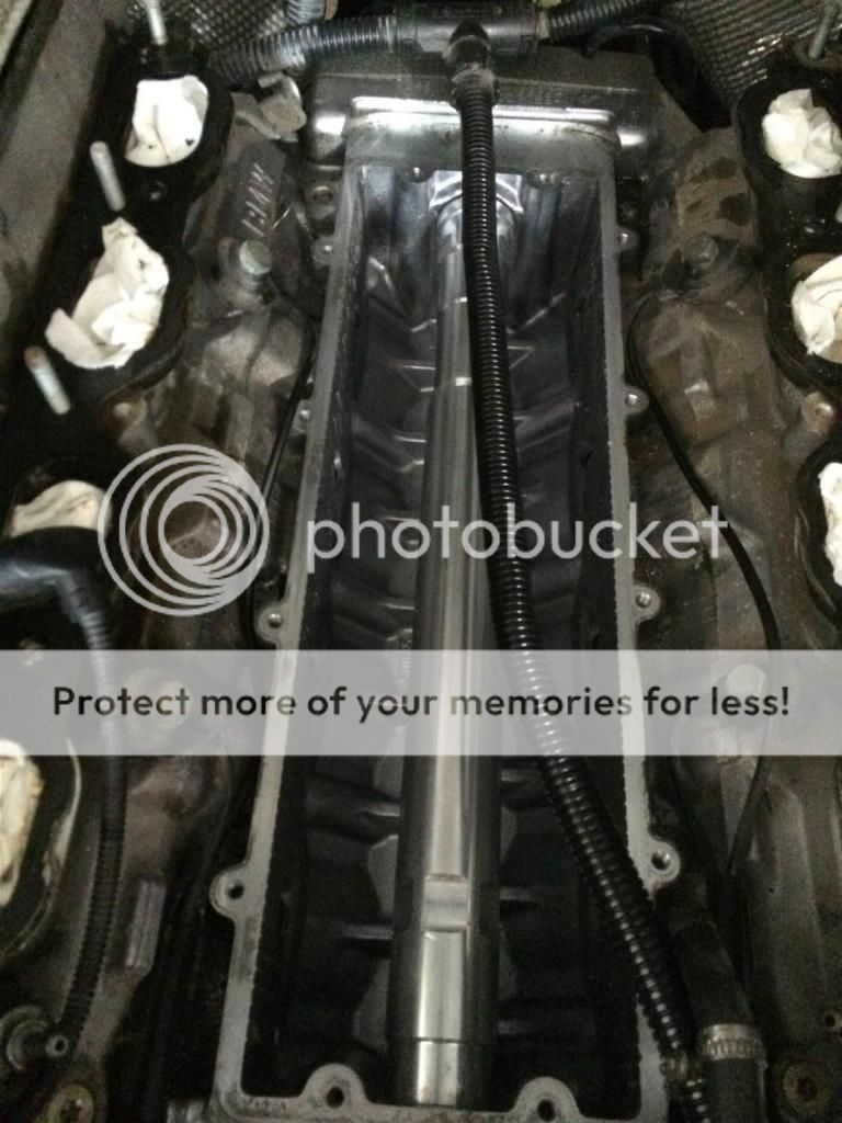 Some pointers:
http://www.realoem.com/bmw/enUS/show...diagId=64_1412 This is the vid from AGA how to replace the seals: BMW N62 Valve Stem Seal AGA Tool - Instructions - YouTube At 15:34 of this vid it tells you how to place the keepers. This can be confusing at first. So here it is: the fat side of the keepers should face DOWN in the keeper tool. They will face UP, once you install them on the valve stem. Be careful here. The AGA tool kit is a must short of pulling the engine. I found 3 tools to be very important: One is a long needle nose pliers, a long needle nose pliers with bent jaws and a thin magnet. You will also need a short version of the long jaw needle nose pliers. The different needle nose pliers will be helpful in different spots where you need to pull the old valve stem seals. The needle nose pliers with rounded jaws did NOT work for me (like the ones in the AGA vid). Here is what I mean: 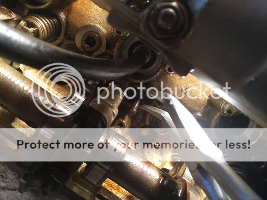 Thin magnet:  Of an important note is what valve stem seals you purchase. Buying BMW OE seals can be a hit and miss. You could end up with the improved version, or you could end up with the exact ones you just pull out, which will start failing 60k later. What you want (I talked with Martin) are the Elring Klinger seals. These have the rubber part made out of Viton - the original ones were made out of ordinary rubber - and also the internal design is different, making them permanent fix. here are some shots: 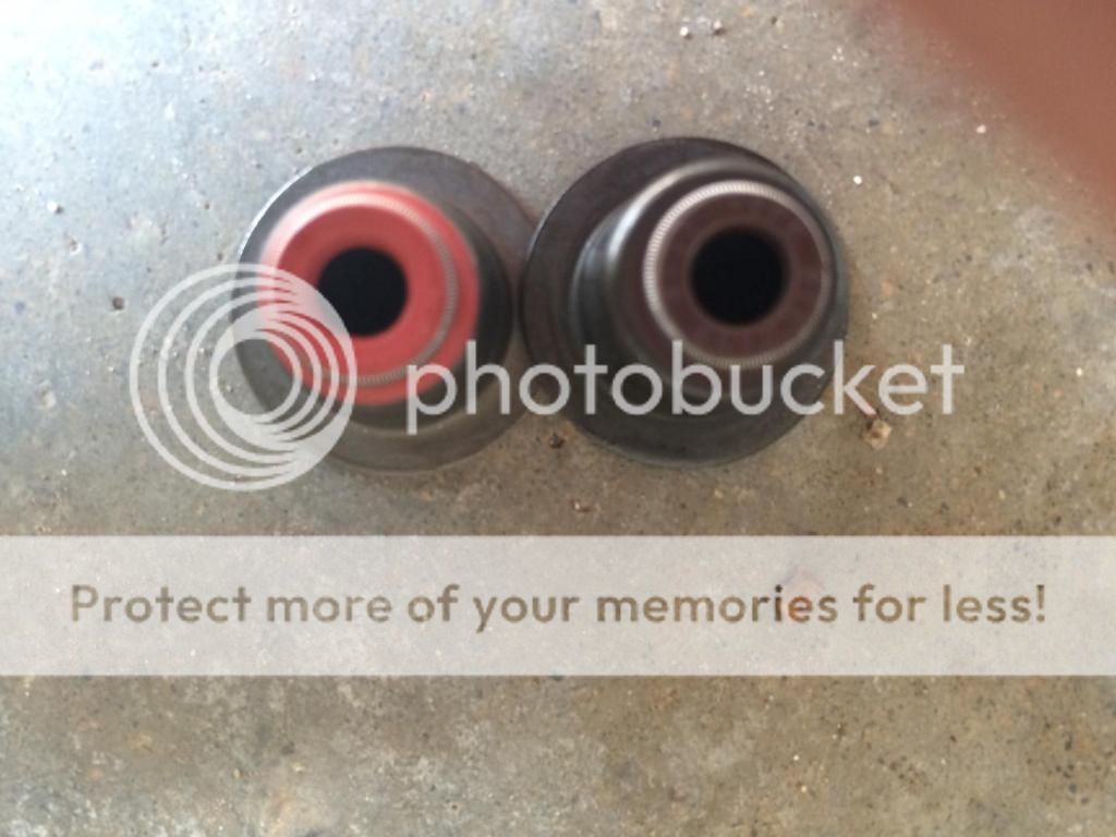 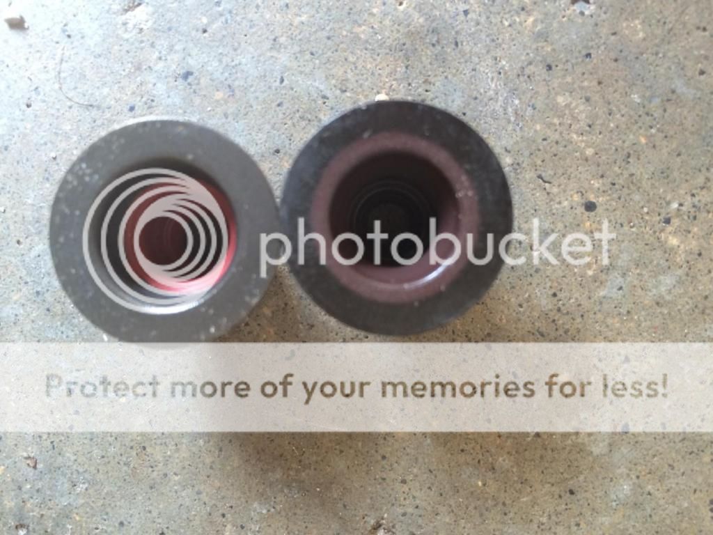 Here is a shot working on bank1: 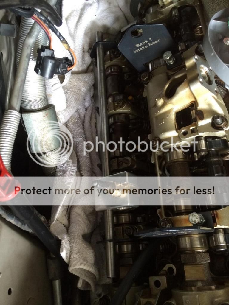 And another one: 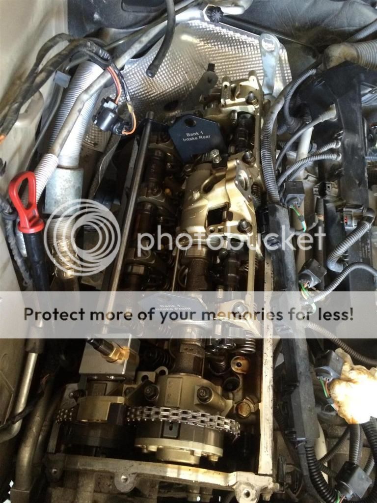 When replacing the seals, also make 100% sure you are at TDC on the cylinder you are working on. The reason is, as you work on one valve, and you move to the next, you might lose compression. Like this: 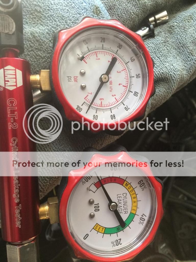 Notice I have 100 psi pressure, but now I have high compression loss. This happened on many cylinders. here is what I found works best. Don't fret, just carry on and do what needs to be done. The valve might slide down, but you can pull it up gently with the needle nose pliers of your choice. The valve usually will stay, and you can place the keepers, etc without the use of compressed air (the valve won't fall down, because it's held by the piston at TDC). Here are a few shots with the valve stem slid on top of the piston, then pulled up with the pliers: 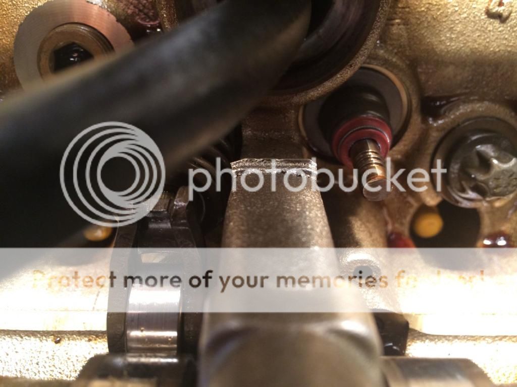 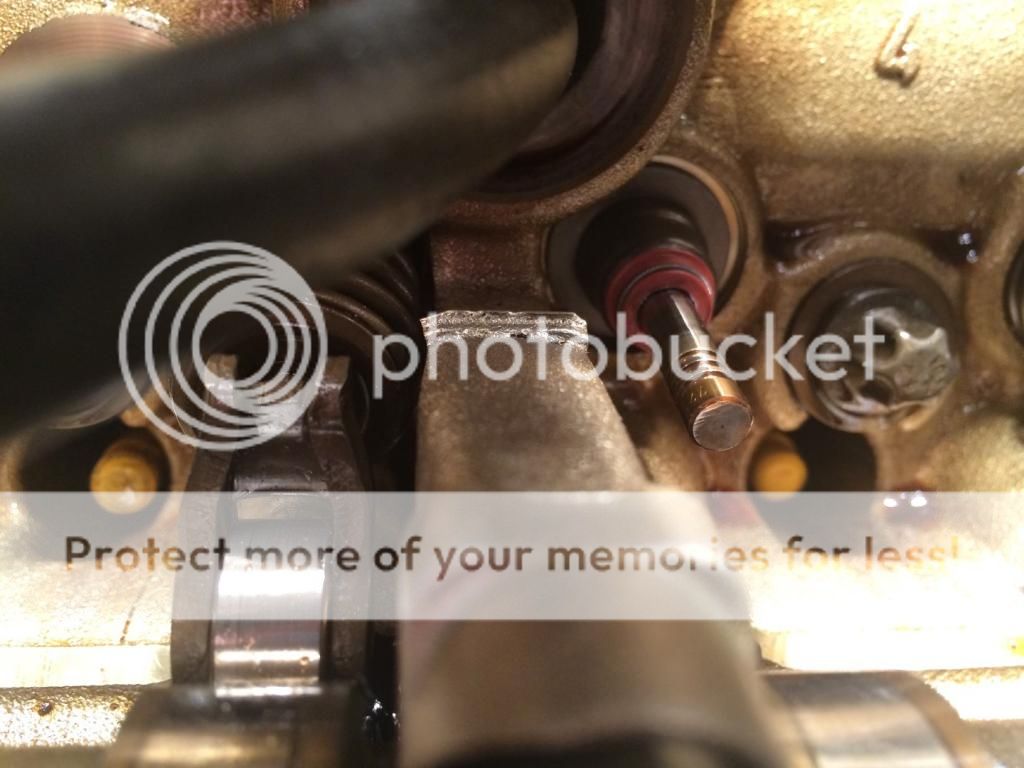 Sometimes though, the valve would slide down as soon as I touched it, making it impossible to place the keepers back. At that point, I used compressed air, although the compression wouldn't hold. But it was enough pressure to hold it up. Bank 2 is a different story. The space is tight, and you need as much room as you can muster by removing also the heater hoses, the hook that holds them, and the heater valve. To remove the hook that holds the heater hoses, you first have to remove the lower cam sensor on top of the left valve cover, otherwise it won't come off. Also, with the hook in place, it will be a bear to remove the valve cover. This here is the culprit: 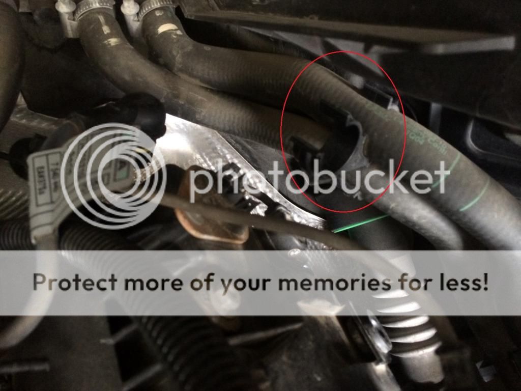 This is the cam sensor that has to come out first (remember to install it last when replacing everything back):  Here are a few shots where the screw of the heater hoses hook is, and how tight the space is (intake):  here are some shots working on the exhaust, on the same bank2 (tight): 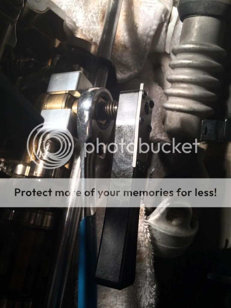 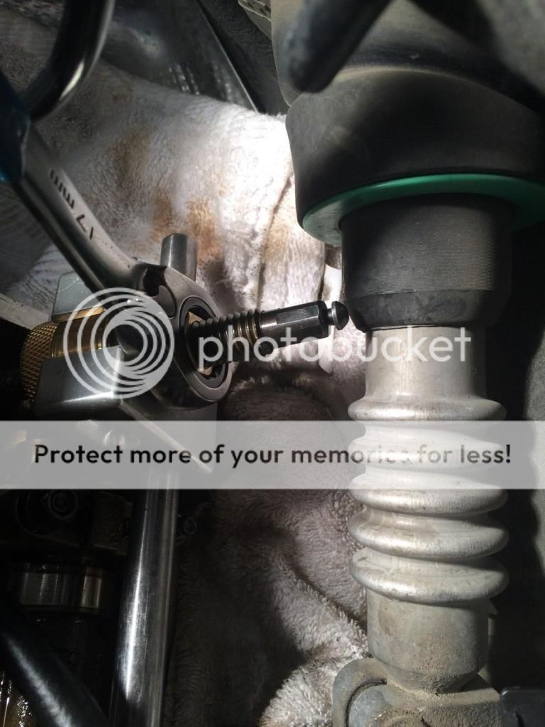 How it looks on the valve stem:  Almost every seal and every gasket were shot at 100k miles, including the upper timing gaskets and the solenoid seals. Take a look:   For the upper timing gaskets I followed this vid: DIY BMW Timing Cover Gaskets N62 engine - YouTube I want to mention the fact that the left side is more difficult than the right side, because the alternator has to slide out. There is one bolt that holds the left upper timing cover right behind it. To slide the alternator, the TIS states to remove the lower pulley, the 2 bolts that hold in place the alternator and slide it out. The truth is, you want to remove the tensioner as well, and also the bracket for the electrical wires, to be able to wiggle the alternator up and down. Don't remove the upper bolt, just loosen it. Remove the lower bolt. The alternator has an "U" bracket - one side you see at the front, one side is behind, you cannot see. Now you have to slide the alternator sideways - as you stand in front of the engine from left to right. A rubber mallet might come in handy. Once you see the front bracket clearing the backside where it was mounted, you can slide the alternator out. You can leave the electrical connections on. Once you have replaced the gasket and the solenoid O-rings, you can place back the bolts that hold the upper timing cover on, tighten the one that is behind the alternator (10 Nm), except for the 2 bolts that hold that electrical wiring bracket. Put some grease on the front and rear end of the alternator "U" bracket, place the upper bolt and only slightly screw it in (a few turns), so now you can slide the alternator back in place - from right to left in a pendulum motion as stand in front of the engine. Then tighten the 2 screws with the electrical bracket. It will make sense once you tackle the job. Later today I will post all the tightening torques from TIS (and what I used). The ISA screws that hold the VVT plate to the engine are very fragile, I remember the tightening torque isn't much, just 6Nm, but one snapped while I torqued it down. This is the reason I mentioned to have 1 or 2 handy in the parts list. Torque values (TIS): Alternator bolt (x2) M10 - 16mm: 43 Nm Pulley (x1) torx : 45 Nm Valve cover gasket: Cap nut (x8) M7 - 10mm: 15 Nm Screws (x5) M6 - 10mm: 10 Nm Oil rail and fasteners after valve stem seals done: A few M6 - 10mm bolts & nuts: 10 Nm Oil rail bolt (1 / bank) M8 - 13mm: 25 Nm Eccentric shaft sensor: ISA screws (x3) M5 (torx) 6 Nm Valvetronic: Torx bolts (x4 long + x4 short) M5 6Nm Upper timing case: Bolts (x8) M6 - 10mm: 10 Nm Vacuum Pump: Torx bolts (x3) M6: 10Nm Forgot to mention: Put rags around the side you are working on to cover any gaps between the engine bay and the engine (see pic #8). Parts can and will fall, and if they fall outside the engine, you might never find them, especially the keepers, which are very tiny. There are also nooks & crannies below the engine where these can get lost. At the front of the opened engine, you can see the timing chain - cover that part also, really tight. When I was almost done, one spring plate slipped out of my hands and went inside that opening. I fished for about 4 -5 hours. There is absolutely no space, and you have no visual, and I was lucky to find the part (lodged between the chain and the crank - there's where the magnet "clicked"). Another update: When I started the car, it had a clack-clack-clack sound on bank1. Exactly like sewing machine. No codes. Phoned Martin from All German Auto, and he told me that he saw a vehicle that was doing the same thing after the repair. He said that vehicle had one of the intermediate levers out of alignment/misplaced. So I opened bank1 up and I found not 1 but 3 springs that didn't sit in the correct position on the intermediate levers. I have no idea how this happened, but it did. Now everything is back and normal. Take a look at this pic, and see where the spring ends (bottom). It does not sit in the "V" groove as it should. So after each of the intakes are done, make sure you double-check that the intermediate levers are also sitting correctly.  Addendum: I was asked a question about TDC - if the flag is up, is this TDC? The only way to know 100%, is to look at the valve stems. One could be at the end of the exhaust cycle, and then the exhaust valves will stay open (remember the cycles of the 4 strokes engine). If you read my post, I mentioned I had 2 - 3 cases, where I lost compression (doing the exhaust valves). This is the reason why. And no, the valves will not fall down in the cylinder. They are still resting on the cylinder.
__________________
Stable: e92is, e46 M54B25, e83 N52, e53 N62 - sold, e39 M54B30 R.I.P. Last edited by Doru; 05-27-2015 at 11:34 AM. 
|
| Bookmarks |
|
|
|
|


 Threaded Mode

