
|
|
|
|
||||||||||
| Xoutpost server transfer and maintenance is occurring.... |
| Xoutpost is currently undergoing a planned server migration.... stay tuned for new developments.... sincerely, the management |
 |
|
|
LinkBack | Thread Tools | Display Modes |
|
#1
 02-17-2015, 04:27 AM
|
|||
|
|||
|
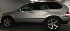
This modification was done on my 2006 4.4i X5 with Xenon and Adaptive headlights. Be sure to check the wiring diagram for your specific car if you decide to take this route. I've attached copies of the wiring digrams of the left and right headlights and the LCM. Here's what I did:
Tools Needed:
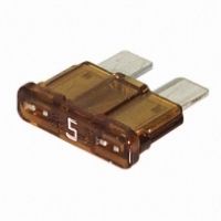
For the 04-06 X5's pin 7 is the AE power wire for both headlights. I did not use the connector on the back of the headlights. I went directly to the AE plug inside the headlight. The LCM has three main connectors: X12 (15-pin Black) X38 (15-pin White) X10117(54-pin Black) The AE's are described as side lights in WDS. The following wires are the signal wires. When the AE's are supposed to be on, the LCM sends power to the AE's to turn them on. By splicing in a jumper wire between the signal wire and a 12v ignition source, we are able to turn the AE's on whenever the key is on. The left AE traces to pin 18 on the x10117 (54 pin black) connector on the LCM. (The wire is Grey with a Green stripe) The right AE traces to pin 3 on the x12 (15 pin black) connector on the LCM. (The wire is Grey with a Blue stripe) Before working on the electrical system of any car, disconnect the battery! Step 1: Remove the trim under the glove box. There are two twist and release connectors and one phillips head screw. 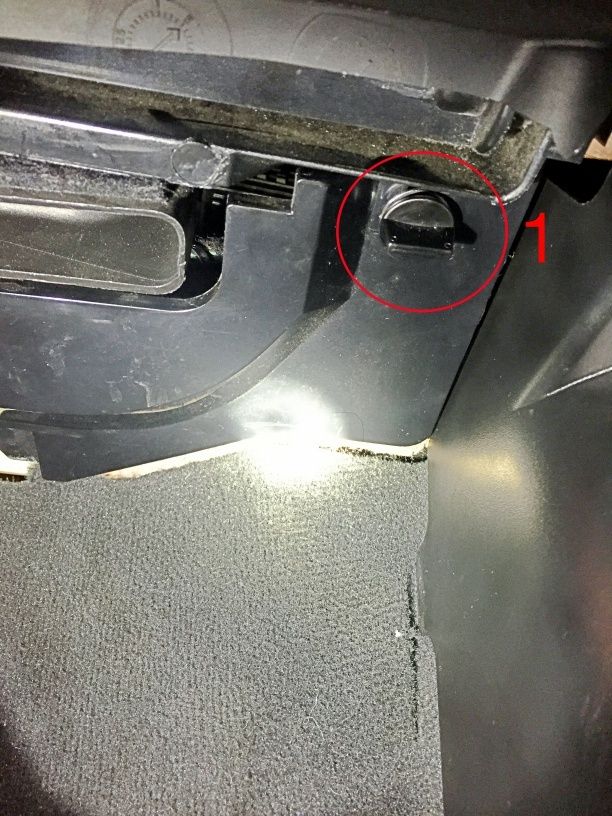 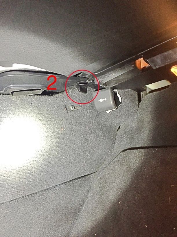 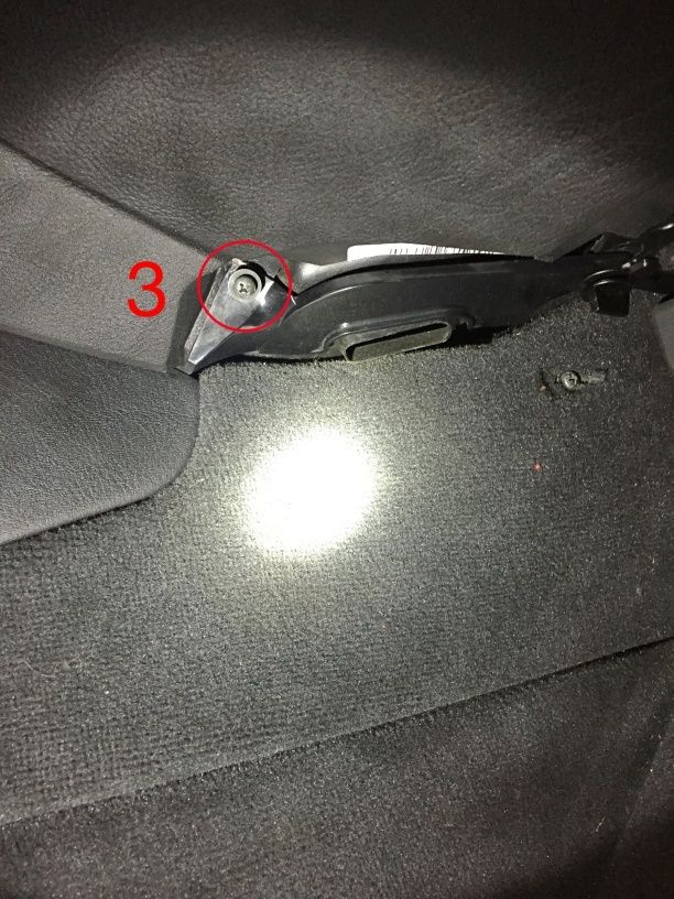 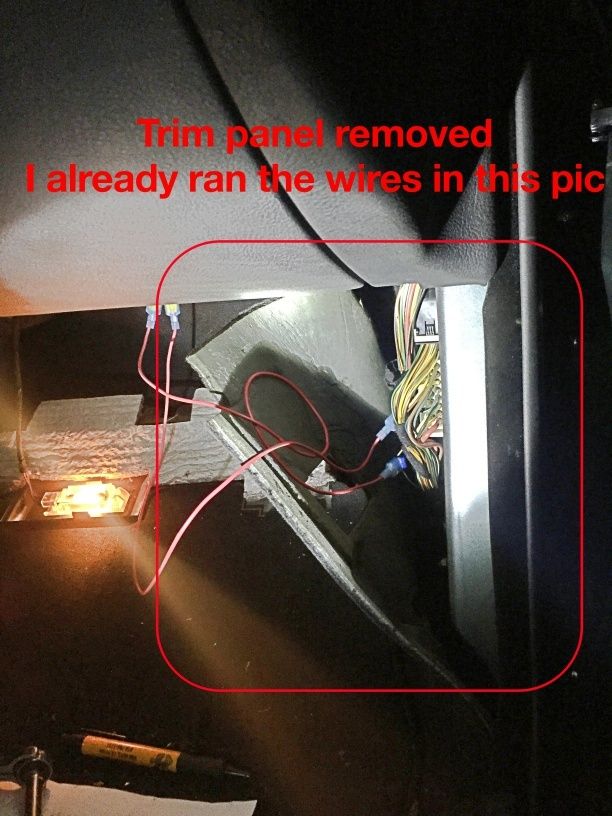 Step 2: Remove the x12 and x10117 connectors and find the wires. Here's a good way to test to see if you have the correct wires. Grab an Volt meter and set it to the continuity setting. If your meter has the function is should beep when you touch the leads together. Probe the wire and the LCM and probe the white wire at the AE connector. If you have continuity, you have the correct wire. 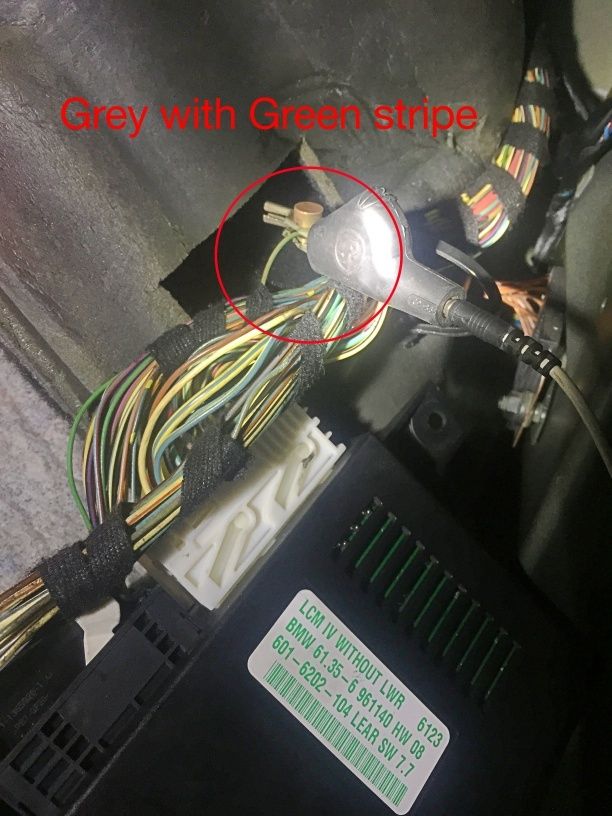 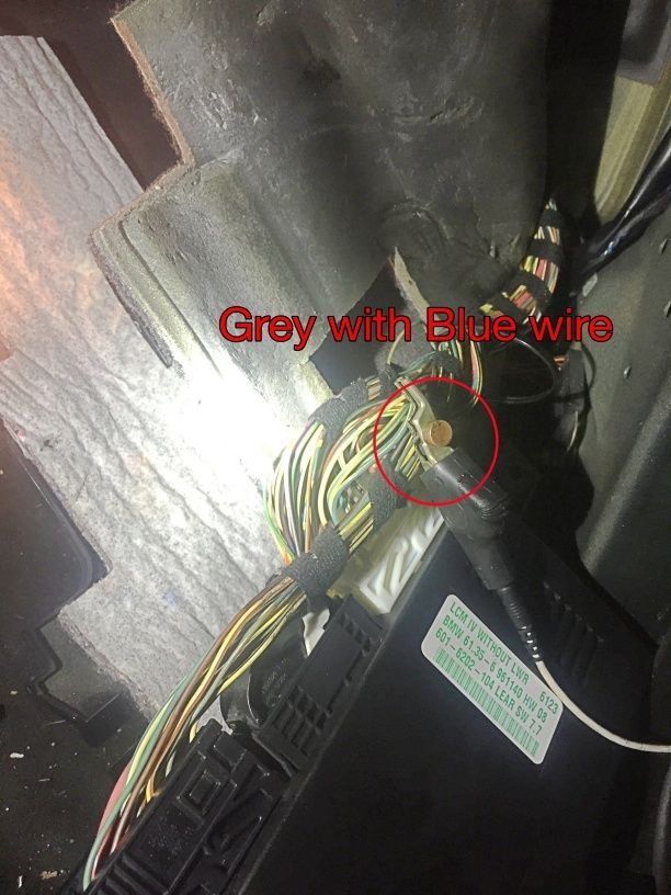 Step 3: Install wire taps on the wires from the LCM. 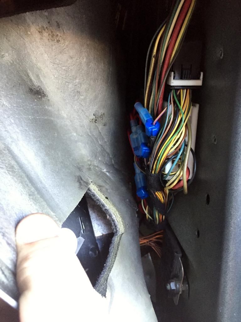 Step 4: Open your fuse box inside the glove box. Remove fuse number 4 (5A). Crimp 2 wires together to the fuse tap and connect a female connector on each wire. 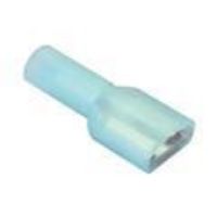 Install your fuse tape in place of the number 4 fuse. Install both 5A fuses into the fuse tap. 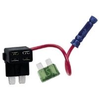 Mine looks a bit different because I modified my fuse and soldered the wires to the fuse. This way works as well but it requires more tools and time. 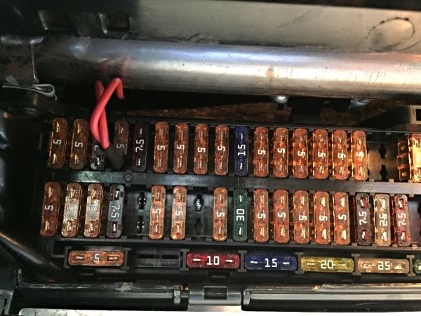 Step 5: Measure out the length of wire you need (two lengths) and crimp on the connectors that will plug into your wire taps. Cut your wires in the middle and install 1 diode in each wire. You will need to solder the diode to the wire or you can crimp it on with a crimp connector. Make sure to use shrink tube or electrical tape to cover any exposed parts of the wires and the diode. You can cut the leads on the diode to make them shorter. 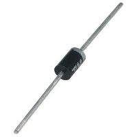 The diode is installed with the line pointing in the direction of flow. You want voltage to go to the LCM wires so you will install the diodes with the lines pointing away from the fuse. Step 6: Connect your jumper wires to your wire taps. Step 7: Plug in the LCM connectors Step 8: Connect the battery and test to make sure everything works. Turn your light switch to the off position and turn the key to position 2. If your AE's light up, congrats! Step 8.1 (trouble shooting): If your AE's do not light up, check all of your connections to make sure they are correct and making contact. Connect one end of your volt meter to the jumper wire and the other end to the white wire on the AE plug and make sure you have continuity. Connect the negative lead of your volt meter to a chassis ground and connect the other end to the white wire of the AE connector and make sure you see 12 volts. Step 9: Put the under panel back on and enjoy your new AE DRL setup. 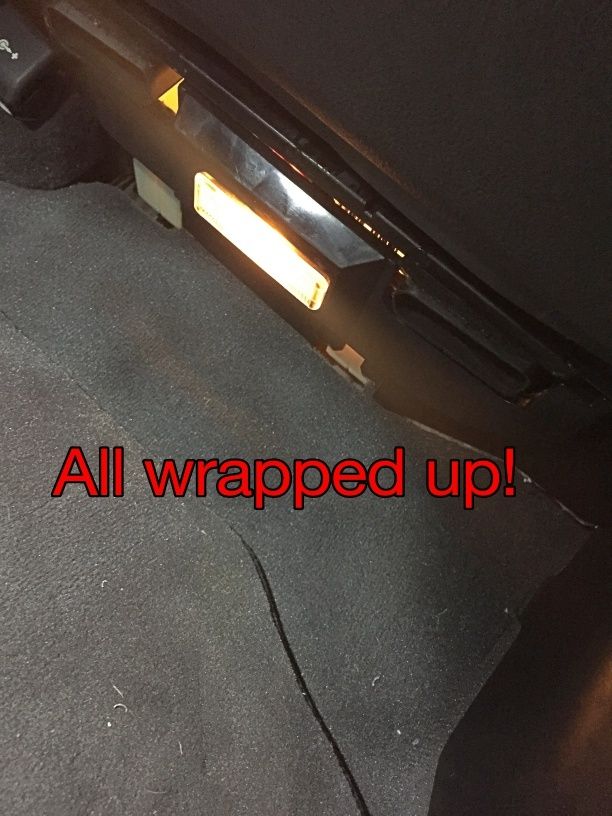 NOTE: This can also be installed with a relay to have the auto dim on/off feature as most of the aftermarket AE's do. Simply find an installation manual for aftermarket AE's and follow the instructions for installation with this feature. The installation technique in this write up makes it very easy to do this modification as all of your wires are near your interior lights so you do not have to run any long lengths of wire. Here are some pictures of the AE bulbs I bought from eBay. The connectors slid right on and off the stock connectors so I had to use a pick to close the female side of the connectors. I added a zip tie to each plug to make sure they don't come apart while driving. 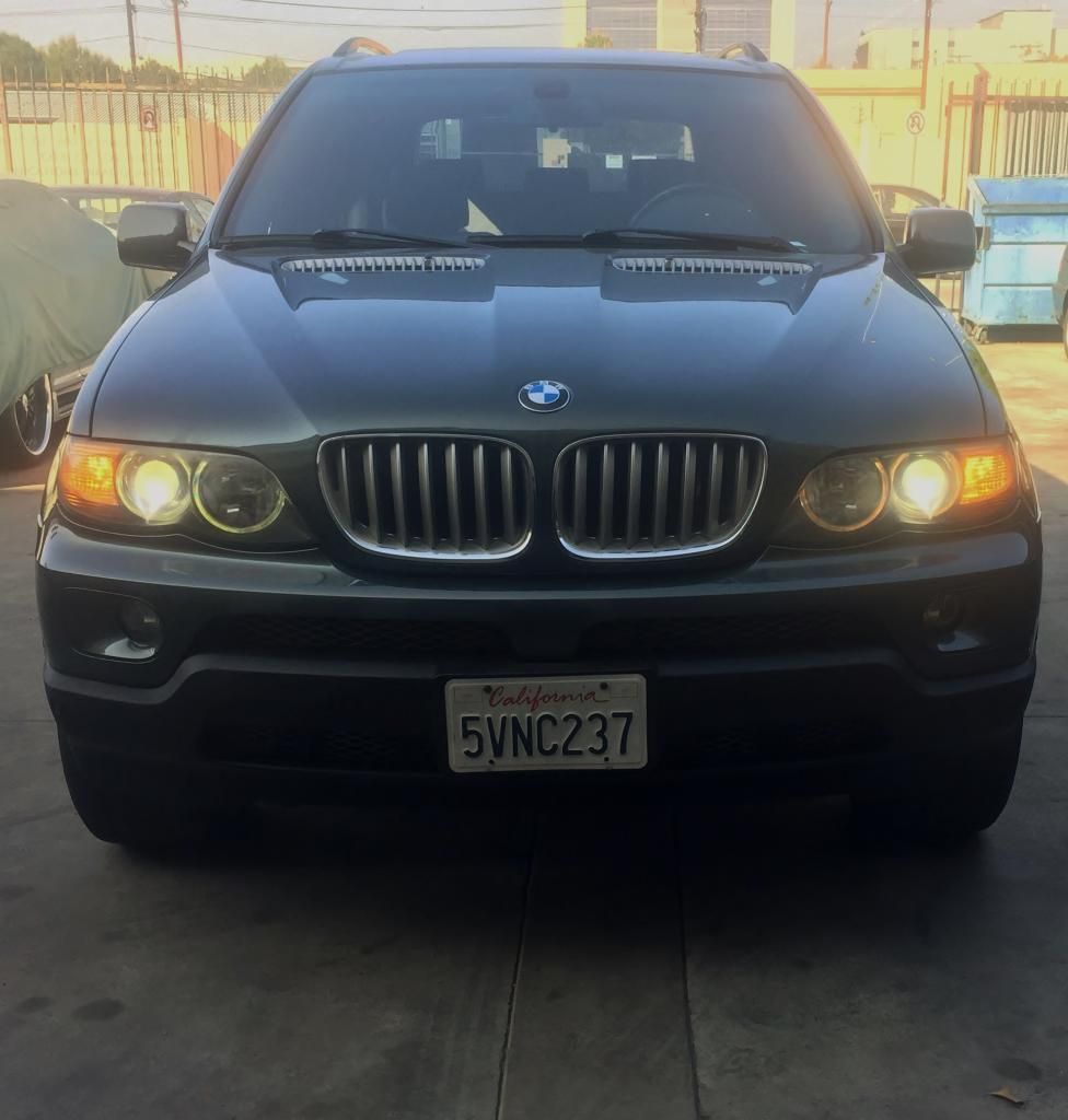 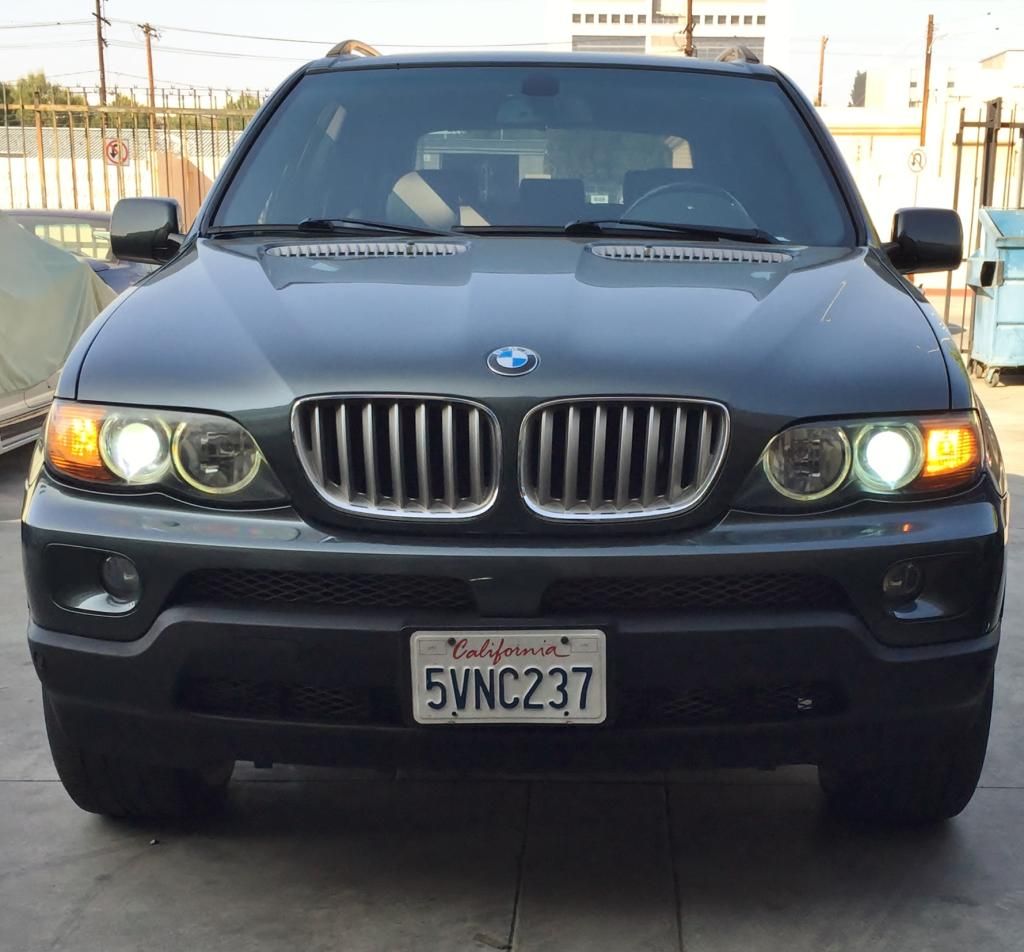 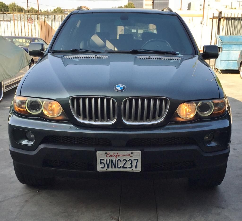 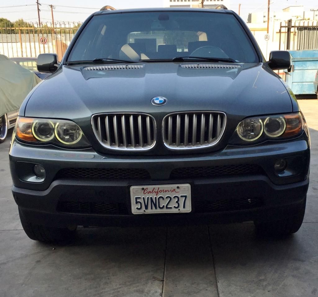 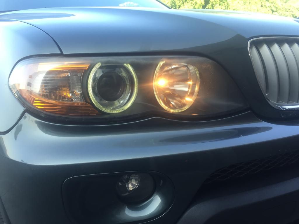 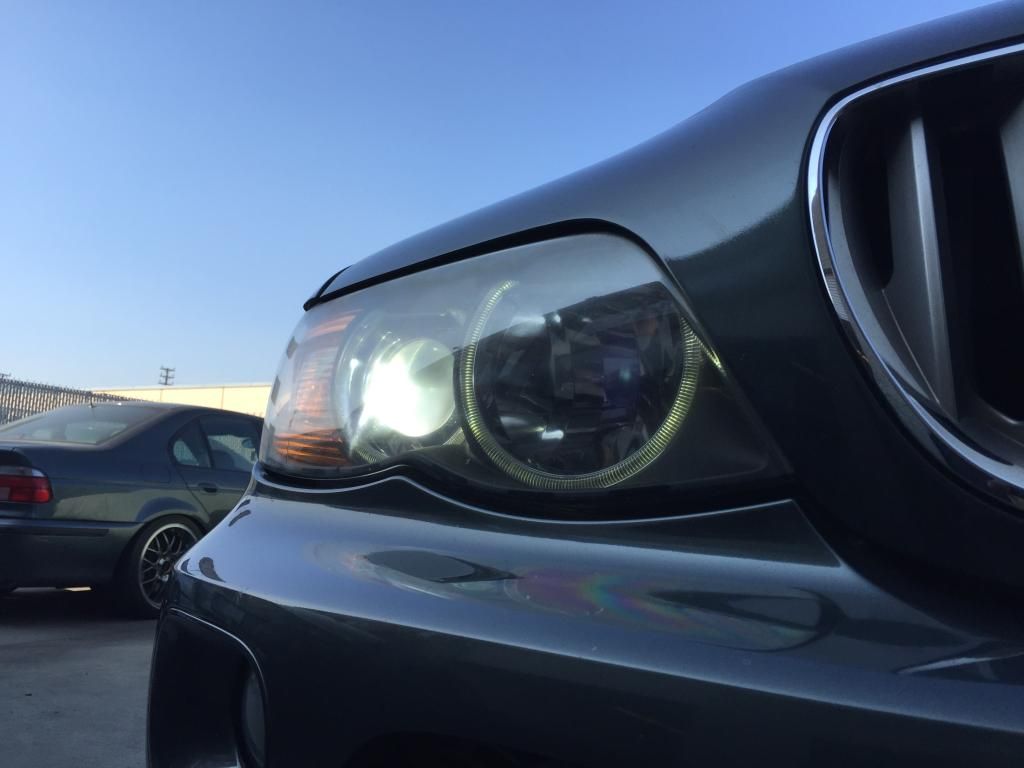 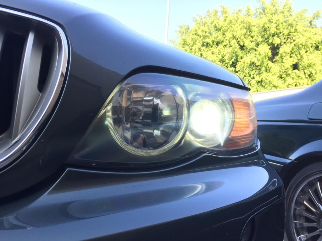
Last edited by THATDONFC; 02-27-2015 at 01:47 AM. 
|
| Sponsored Links | |
|
|
|
|
#2
02-17-2015, 06:17 AM
|
||||
|
||||
|
Thanks for the detailed write up. This is on my 'to do' list this weekend. Unfortunately your pics aren't showing for me?
__________________
2005 3.0d Sport - Sapphire Black Engine : Bluefin Superchip Tune, Wheels & Sus: Style 168s (10.5s all round), H&R RDA Spacers, Bilstein B12, Eibach 40mm drop, Whiteline RSB Exterior: Le Mans flares, 4.6is kit F&R Interior: Dynavin N6, Blackvue DR650 dash cams My Build Thread: http://www.xoutpost.com/bmw-sav-foru...run-sheet.html
|
|
#3
02-17-2015, 06:22 AM
|
|||
|
|||
|
Quote:
EDIT: Pics should be working now. Last edited by THATDONFC; 02-17-2015 at 06:34 AM.
|
|
#4
02-17-2015, 08:22 AM
|
||||
|
||||
|
Pics not working showing for me.
Need to do this project. Your DIY seems easier. I've got the wiring sitting in my garage for several years. Thanks for the write up.
__________________
'05 E53 X5 4.4i, '97 E39 528, '07 E92 335i, '16 F86 X6M.
|
|
#6
02-17-2015, 11:01 AM
|
||||
|
||||
|
Nice idea for those not willing to crack open the headlights and install their own AE units. Nice writeup.
Pictures not working on my end either though.
__________________
2005 X5 4.4i Build 04/05 Maintenance/Build Log Nav, Pano, Sport (Purchased 06/14 w/ 109,000 miles) (Sold 8/15 w/121,000 miles) 2006 X5 4.8is Build 11/05 Maintenance/Build Log Nav, DSP, Pano, Running Boards, OEM Tow Hitch, Cold Weather Pckg (Purchased 08/15 w/ 90,500 miles) 2010 X5 35d Build 02/10 Nav, HiFi, 6 DVD, Sports Pckg, Cold Weather Pckg, HUD, CAS, Running Boards, Leather Dash, PDC, Pano (Purchased 03/17 w/ 136,120 miles)
|
|
#9
02-17-2015, 12:28 PM
|
|||
|
|||
|
Quote:
|
|
| Bookmarks |
| Tags |
| angel eyes, angel eyes e53, drl, e53 |
|
|
|
|


 Linear Mode


