Home Forums Articles How To's FAQ Register
Go Back   Xoutpost.com > BMW SAV Forums > X5 (E70) Forum
Arnott
User Name
Password
Member List Premier Membership Search Today's Posts Mark Forums Read

Xoutpost server transfer and maintenance is occurring....
Xoutpost is currently undergoing a planned server migration.... stay tuned for new developments.... sincerely, the management


Reply
 
LinkBack Thread Tools Display Modes
  #1  
Old 11-18-2019, 08:22 PM
Member
 
Join Date: Nov 2018
Location: San Diego
Posts: 130
ucsbwsr is on a distinguished road
Custom Turbo Inlet System for my X5D

I wanted to share a recent project on my X5D.

Disclaimer: This isn't a step by step guide however for those inclined DIYers all the critical information is covered and the process is outlined, there should be adequate information to build your own replica if you fancy. Follow at your own risk, do your own research, and take responsibility for your work. No that this is done....

The goals:
- Improve turbo response by shortening intake length and increasing air flow potential
- Retain "cold" air source
- Simplify system to make engine access easier
- Clean OEM+ aesthetics

I have yet to confirm the performance gains of the system but once I get my X5 tuned I plan to get some back to back dyno runs comparing the custom inlet vs stock airbox. I would love to find a race shop that can bench dyno the CFM too. This system was "engineered with common sense" so it would be nice too see some data to confirm the increase in performance
....or show that I wasted my time Hopefully #CommonSenseEngineering prevails.

Here is the parts list, if they were modded those details are below:

- K&N RC-5000 Filter
- K&N RC-70031DK Dry-Charger
- 3.5" 45 Elbow
- 3.5" 90 Elbow (4" legs recommended)
- 3.5"-3" Reducer (3" length)
- 3.5" Aluminum Joiner
- HPS SSWC-59-83 x1
- HPS SSWC-84-108 x4
- Pro Fabrication 3.5" Oval 90 Pipe
https://www.profabrication.com/3-5-x...l-bend-ms.html

Parts ran me ~$300

Here was when the idea was conceived. Happy to say this state-of-the-art scribble turned out to be fairly accurate.


The star or this inlet system is the 3.5" 90 degree oval piping as retains the 3.5" diameter while clearing the hood once it's shut. Originally I was looking at a 3.5" oval pipe from CX Racing that was aluminum but I went this Pro Fab pipe because it has a tighter 4" radius, I called CX Racing and asked them for the specs but they didn't know (must be lost in China somewhere, lol). If I had to guess the CX piping is 4.5-5" radius, either way the 4" of the Pro Fab is extremely helpful.

*This Pro Fab pipe is mild steel and starts to rust if you look at it wrong so plan to seal/protect it somehow.

Here is the original pipe being test fit


In an ideal world I would maximize the amount of metal and minimize the amount of silicone used to construct the inlet but the direct routing to the turbo meant form will follow function. Here is what I was eyeing up.


The oval pipe fit snugly into the oem hole in the shroud but the pipe needed to sit lower for hood clearance. This is without trimming, notice the height relative to OEM.


If you look closely at the edge of the green tape you can see there was a circular cutout in the radiator shroud so I trimmed the plastic on top and did my best to make a clean cut.


I did an initial trim of the oval pipe.


With the oval pipe and the radiator shroud trimmed fitment was much better, notice how low the pipe sits now, very similar to the stock snorkel.


I had to take some more length off the oval pipe to help straighten the routing. Here is after final trimming. I don't have the exact measurements but there is about 1" of leg (past radius bend) that goes towards the filter, the other end which runs to the turbo is slightly longer with ~2" of leg.


Here is the OEM turbo inlet removed from the X5


We won't be needed the top part and thankfully the PCV connection is built into the lower pipe. With the upper portion removed I noticed there was a large flange, this isn't ideal.


Using a sanding wheel I removed the outer lip and bored out the inside to make a nice smooth transition.


For good measure I bored out the MAF as well.


This is the 3.5" joiner I use between the silicone 90 and 45. It has a bead as it's intended to be used as charge piping.


That bead will only disrupt air flow so I trimmed off each bead to keep things smooth. Not pictured but you can notice this when observing the final product but I stuck this 3.5" pipe in my bench vise and made it oval to help keep continuity in the shape of the piping.


If you look closely you can see the oval piping is slightly concave on the long sides, this is a byproduct of the bending process.


To alleviate this I used some JB Weld to fill in the small dips on all 4 sides.


After the JB cured over night it was time to sand, clean, prep, prime, and paint. I used some high temp stable engine paint and added further protection with a top layer of ceramic coating. Hopefully this resists paint chips when I inevitably remove the inlet for more wrenching.


Once I got the general routing of the system down my attention focused on filter location. I was adamant about the filter being vertical and NOT contacting the shroud or radiator, or poking through towards the kidney grills so aligned the filter where I wanted it and worked backwards aligning and trimming if needed.

After achieving ideal filter location and confirming there would be no contact with the hood shut I looked into ways to secure the system. I was thinking about L-brackets and all kinds of serviceable mounting solutions but once I had the system mocked up I realized the system was fairly rigid. The silicone does offer some flex but considering the short length of the system overall and the M57 doesn't seem to move much underload, the intake wasn't flopping around, it was barely moving at all. My solution was using a small rubber disc I had laying around, I attached some 3M VHB, and use this is a locating /buffer for the hose clamp. After some test drives and manyu WOT pulls I confirm this works like charm. The only contact points for this whole system are this and where the OEM turbo inlet bolts to the turbo. Very happy about this.


*Depending on what length 45 degree silicone elbow you buy your trimming may differ but I took about 1" off each end of mine. Also the 90 degree silicone elbow w/ 4" legs was also trimmed, I took about 1" off the end that connects to the MAF.

*Also not pictured but the opening of the K&N filter is larger than the 3.5" oval piping. The trick is to take one of your 1" silicone trimmings and use that as a spacer. -Slide the 1" long ring of silicone onto the forward edge of the oval pipe and then install your filter, works like a charm and you can recycle! Look closely at the pics below and you can see the silicone sticking out where the filter mounts.

For added security you can add a K&N Dry-Charger which is a hydrophobic filter guard, great for dust and water.


Let's first take a look at the stock intake system


...and a peak inside, notice the entire filter is not utilized


Now the final product


Installed
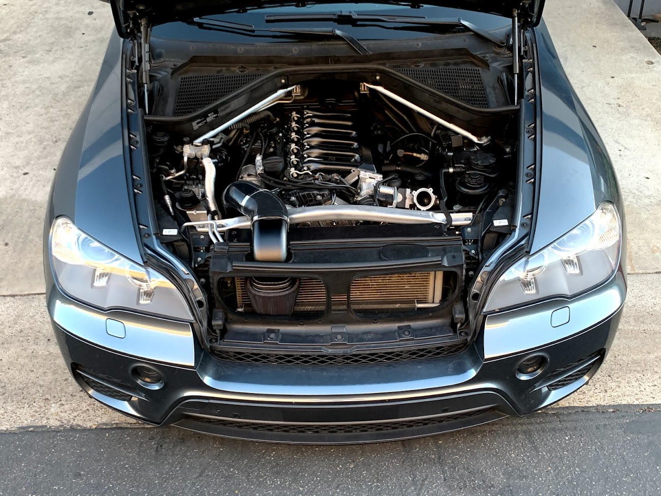

Reply With Quote

Sponsored Links

  #2  
Old 11-19-2019, 01:16 AM
ard ard is offline
Member
 
Join Date: Mar 2006
Location: Sierra Foothills, California
Posts: 6,730
ard is on a distinguished road
Congrats on the effort.


Changing the cross section through the the MAF is, as they say, no bueno


Any opinion on why BMW didnt hang a K&N cone filter out in front of the grill?
Reply With Quote
  #3  
Old 11-19-2019, 01:53 AM
Member
 
Join Date: Aug 2016
Location: Brooklyn, NYC, NY
Posts: 365
robnitro is on a distinguished road
This is why:

Nice craftsmanship but I hate to say it but our stock filter is huge and not a restriction. Even with it dirty, I reach at most 1-2 in h2o on my restriction gauge. Max 30 psi and all the way to redline (max mass flow is at high rpm and high boost). We have more of an issue with exhaust manifold pressure as tuning goes up.
If you take that k+n and unwrap the filter element and measure surface area vs the stock panel filter it will be close. My money is on the stock filter having more surface area. This would be a great mod on the 335d where they have an overly restrictive filter.

The piping is not a restriction at all. It's bigger all over cross section area wise than what the turbo inlet takes in.
Reply With Quote
  #4  
Old 11-19-2019, 09:50 AM
Member
 
Join Date: Nov 2018
Location: San Diego
Posts: 130
ucsbwsr is on a distinguished road
Quote:
Originally Posted by ard View Post
Changing the cross section through the the MAF is, as they say, no bueno
Care to elaborate?

Quote:
Originally Posted by ard View Post
Any opinion on why BMW didnt hang a K&N cone filter out in front of the grill?
....because they are a large global auto manufacturer that is making a utility for many markets and selling it with a warranty to they are conservative with their designs to avoid warranty issues, recalls, etc.
Reply With Quote
  #5  
Old 11-19-2019, 10:45 AM
Member
 
Join Date: Jan 2018
Location: NY
Posts: 45
Dieselfan is on a distinguished road
Wow! Congrats!. I like it very much.

Are you going to mass produce the kit? I'll be the first to order.
__________________
10 X5 35D
02 530 SC
07 X3 3.0IS 6MT
01 330XI
97 528
Reply With Quote
  #6  
Old 11-19-2019, 11:16 AM
Member
 
Join Date: Nov 2018
Location: San Diego
Posts: 130
ucsbwsr is on a distinguished road
Quote:
Originally Posted by Dieselfan View Post
Wow! Congrats!. I like it very much.

Are you going to mass produce the kit? I'll be the first to order.
I don't plan on selling it as a kit, there is a little bit too much customization required with these parts. If the demand is high enough then I might revisit it but first thing is to see how it performs.
Reply With Quote
  #7  
Old 11-19-2019, 12:51 PM
ard ard is offline
Member
 
Join Date: Mar 2006
Location: Sierra Foothills, California
Posts: 6,730
ard is on a distinguished road
Quote:
Originally Posted by ucsbwsr View Post
Care to elaborate?
Uh, before hacking up the intake, maybe Google 'how the MAF works'

A MAF ELEMENT measures the VELOCITY of air at a specific point. The sensor is mounted in a tube, with the sensing element placed within the air path at a known point.

Engineers use their knowledge of the flow profile AND CROSS SECTIONAL AREA to then convert the point reading of m/sec into a reading that represents density (gr/mm3) times cross section mm2 times velocity m/sec:

Gr/mm3Xmm2Xm/sec= gr/sec. (Or usually kg.sec, just scaling)

When you open up the cross section, by say 5-10%, you can materially and significantly change the calibration....

Consider a given volume of air moving through the stock MAF....that volume will result in a value of say 3.2Volts at the MAF.

Now take a MAF in which the cross section has been increased by 10%. That same volume will now only create a MAF signaled 2.9V.

The DDE will say "Oh, only 2.9V? I will add fuel that my map says is right for 2.9V of air". (But really it SHOULD be adding fuel for 3.2V, it is actually getting 3.2V worth of air....). It will be running lean.

There is a signficant amount of engineering data on MAFs that you can find on line. Once you start messing with MAF calibrations, you need something much more that standard 'tuning' one might buy off the shelf.


Quote:


....because they are a large global auto manufacturer that is making a utility for many markets and selling it with a warranty to they are conservative with their designs to avoid warranty issues, recalls, etc.
lol,

And they leave 50HPs on the table, easy to just slap some parts on and grab em, eh?

Same BS is used to sell a TON of do-nothing air filters and intake.....

I can see your efforts on normally aspirated engines...but with a turbo sucking in air, minor restrictions in an intake are usually immaterial.
Reply With Quote
  #8  
Old 11-19-2019, 01:25 PM
Member
 
Join Date: Nov 2018
Location: San Diego
Posts: 130
ucsbwsr is on a distinguished road
Quote:
Originally Posted by ard View Post
Uh, before hacking up the intake, maybe Google 'how the MAF works'
Woah dude, not sure why you are getting so triggered by this intake system. I appreciate constructive feedback but if that is your intention you are going about it the wrong way, it seems to me like you are negatively nit-picking the project without having your facts straight.

As for the MAF housing, take a moment to look at my photo, I merely sanded down the edge 1-2mm to help it pair to the adjacent silicone, it's not a significant change. Also, IT IS AFTER THE MAF SENSOR. I don't see how what I did would have any impact on the MAF reading.

I 100% disagree with your statement about N/A vs turbo, turbo motors have a lot to gain with less restriction and the power potential is much greater than an N/A motor.

Last edited by ucsbwsr; 11-19-2019 at 03:37 PM.
Reply With Quote
  #9  
Old 11-19-2019, 01:37 PM
Member
 
Join Date: Jan 2019
Location: New Jersey, USA
Posts: 161
spyro235 is on a distinguished road
I'm an aerospace engineer by trade, and I see nothing wrong at all with his MAF modification. I even thought it was before the actual sensor, but as long as the cross section didnt change on the plane which the sensor sits, it won't affect the reading at all. Smoother airflow creates a better reading.

And... turbo motors gain a TON from freeing up restrictions. They have much more to gain, in fact, than an N/A motor. I'm not knowledgeable about where the restriction is with this specific platform, but ucsbwsr plans on dyno testing the setup, on the same dyno, on the same car, against the stock. He seems to be doing proper research, on a platform that isn't SUPER well researched (in a publically documented manner).

Looking forward to seeing the graphs! Haven't decided if I'll go for this because of the added in cabin noise, but it's awesome to have an innovator in an X5d.
__________________
'10 X5 35d- 279k mi, deleted and DUDMD stage 2, daily and tow vehicle
'01 330i- Drift car: SLR Super angle, BC coils- keep it simple
'07 335i 6mt - Sold @ 171k miles- stage 2 daily commuter for 2 years
Reply With Quote
  #10  
Old 11-19-2019, 02:32 PM
ard ard is offline
Member
 
Join Date: Mar 2006
Location: Sierra Foothills, California
Posts: 6,730
ard is on a distinguished road
Quote:
Originally Posted by ucsbwsr View Post

I 100% disagree with your statement about N/A vs turbo, turbo motors have a lot to gain with less restriction and the power potential is much greater than an N/A motor.

lol


Sure.


Turbos have more to gain JUST BY TWEAKING THE MAPS. You dont need crazy intake and exhaust mods- just dial up more boost. This part is universal.


Carry on.

Last edited by ard; 11-19-2019 at 07:31 PM.
Reply With Quote
Reply

Bookmarks

Thread Tools
Display Modes

Posting Rules
You may not post new threads
You may not post replies
You may not post attachments
You may not edit your posts

BB code is On
Smilies are On
[IMG] code is On
HTML code is Off
Trackbacks are On
Pingbacks are On
Refbacks are On


All times are GMT -4. The time now is 12:00 PM.
vBulletin, Copyright 2024, Jelsoft Enterprises Ltd. SEO by vBSEO 3.6.0
© 2017 Xoutpost.com. All rights reserved. Xoutpost.com is a private enthusiast site not associated with BMW AG.
The BMW name, marks, M stripe logo, and Roundel logo as well as X3, X5 and X6 designations used in the pages of this Web Site are the property of BMW AG.
This web site is not sponsored or affiliated in any way with BMW AG or any of its subsidiaries.