
|
|
|
|
||||||||||
| Xoutpost server transfer and maintenance is occurring.... |
| Xoutpost is currently undergoing a planned server migration.... stay tuned for new developments.... sincerely, the management |
 |
|
|
LinkBack | Thread Tools | Display Modes |
|
#1
 05-30-2014, 05:18 PM
|
|||
|
|||
|
35d: adding crankcase breather oil separator
--------------------- PART 1 I've been at this for some time tinkering with the idea of reducing oil particles going through the intake via the crankcase breather. The issue is not really so much about oil consumption that is very well manageable at about 1 quart every 10K miles. The issue is actually about tar build up in the intake manifold resulting from the oil mist mixing with the soot from the HP EGR. The crankcase breather is in the back of the valve cover (note: this picture from a slight different version of the M57 than what the 35d has, but the location is the same... More on the difference later) 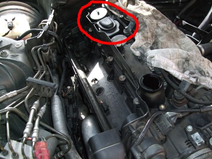 I researched the history of BMW approach to this in the M57: Design #1 The original solution had an actual filter in it. Through some research I found that the same design was used by Land Rover. While Land Rover had the filter as a maintenance item necessitating replacement every 20k-30k miles, BMW never did. This result in the filter clogging up resulting in high crankcase pressure, which ultimately caused issues with the turbo lubrication. That filter was very effective at removing oil particulates from the crankcase gasses, but required maintenance. I think at this as what the quintessence of the German Engineer designed before sales and marketing got involved... Here's how that filter looked like:  Design #2 Sales & marketing gets involved, so as opposed to making the filter a maintenance item (it's not terribly hard to get to it and replace it, but BMW has an ongoing effort, right or wrong that is, to cut down on maintenance requirements) they replaced the filter with a cyclonic separator. Conceptually it works like the Dyson vacuum cleaner: it is free flowing so there's nothing to clogs or maintain. It's not as effective as the filter so some diesel owners in Europe go back to the old design to cut back on oil going through the intake and make it maintenance item. Here's how it looks: 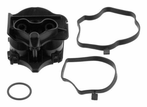 Design #3 Lastly it appears BMW has redesigned the valve cover all together which now incorporates the separator which is of the maintenance-free cyclonic type. My dad has a 325d with the M57 and although the crankcase breather assembly looks as the one above, once removed there's neither a filter nor a cyclonic separator, hence my deduction that the oil separation function is built into the valve cover design (that is unless sales & marketing took over engineering and decided to get rid of such nonsense and let the oil flow). Our X5 has slightly different breather assembly since the line that goes from the valve to the intake is not built into the valve cover. Nonetheless, there is no separator of any kind between the breather valve and the valve cover. Here's how our valve looks like: 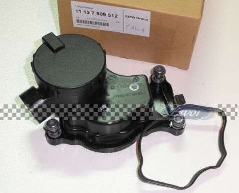 -------------------------------------- So at the end of the day after a bit of homework I concluded that the initial design is very effective at removing oil particles, but not being maintenance-free prompted BMW to redesign the system. The result is a less effective yet maintenance-free solution. For me, as for others who have retrofitted the filter, the benefits of better oil separation outweighs the additional maintenance requirements, particularly since carbon (or better yet tar) build up has somewhat of a precedent in the US version of the M57 that allegedly has more aggressive EGR maps. This is particularly true on the 335d which, again speculations, not having a LP EGR (which is picked up after the DPF) recirculates only unfiltered gasses. From what I observed soot is a very dry particles that makes me conclude that in and of itself soot doesn't build up excessively; it is soot mixed with oily vapors that builds up in a tar like obstructive crap -------------------------------------- Unfortunately since our breather valve assembly is different design, the filter is not a simple drop in, just like it would in, for example, my dad's 325d. It just wouldn't fit. So for the past couple of weeks I've been looking at way to fit an external oil separator (like the Mann+Hummel ProVent) but have yet to find an elegant and easy way to do it. Not to mention the annoyance of having oil collecting somewhere that makes the car looks like it has some sort of incontinence. And, last but not least, it is technically for "off road use only" in California which could result in failing visual inspection: so whatever I come up would need to be easily reversible so I can but it back to stock once inspection time comes... Then I came across something in the TDI world called the "Old Navy CCV" (CCV Mod - Page 2 - TDIClub Forums): it's basically a guy who has milled out of aluminum a CCV housing with a filter to remove the oil particulate. The TDI, even more so than our cars from what I've seen collect oil in the intake and inter-cooler. At the beginning I didn't give it too much thoughts as my head was elsewhere looking for a standalone separator. But then I realized that the very same concept can work for us: what about adding some filtering media in our assembly? There is a fair amount of room where some filtering media would fit very well, just like in the Old Navy CCV 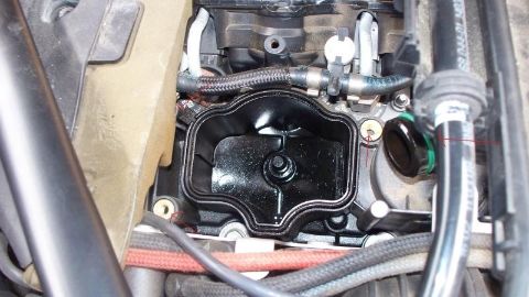 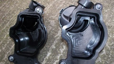 Oil would get trapped in the medium and drain back. Every 20k or so mile would would remove 3 bolts, wash it with some gasoline and you're good to go. Last edited by ZetaTre; 05-30-2014 at 05:36 PM. 
|
| Sponsored Links | |
|
|
|
|
#2
05-30-2014, 05:19 PM
|
|||
|
|||
|
PART 2
I guess I'll go on and use this thread to document this project: here's the execution. I think a good approach is to stage the filtration: I figured I'll have a first layer of low density media, a second layer of higher density, and maybe a third layer. At the top I'll have a stainless steel baffle to hold the media in place, provide further oil separation and actually create sort of an air gap between filtering media and the exit. Now comes the fan part... I was at Lowe's and I think I've found what I thing is a great media: 3M stripping & finishing pads (basically the same material that the Old Navy PCV used, so it's tested to work in these conditions). For Stage 1 I bought 3M Heavy Duty Stripping pads, while For Stage 2 I bought 3M Final Finishing pads. 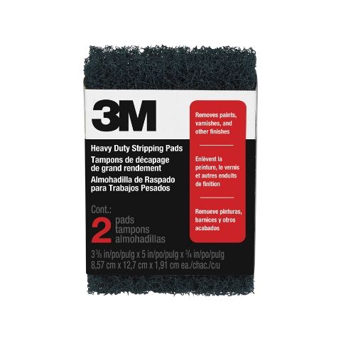 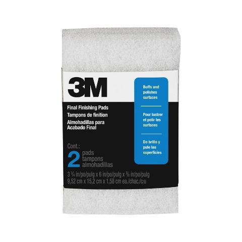 The Stage 3 I'm still not sure if I'll have it, but here's what happened. Before I started going down the current route, I was looking at adding an external oil separator so I went ahead and bought a Mann Provent 200. It looks like this: 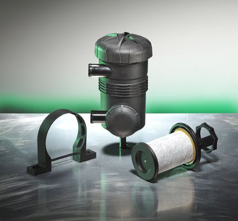 As you can see inside there is a filter. I haven't received it yet, but the idea is to look at possibly unraveling the media from the filter and use it as Stage 3... Since I haven't got a chance to dissect it yet, I don't know if it's big enough; maybe it can even be the only stage I'll use, but then I'll have to figure out a way to hold it in place. Anyhow, I guess that would be considered for the next sprint... Last part is the baffle. At a closer look to our CCV assembly I noticed on the inside a sort of groove (highlighted in the second picture) that would work perfect to hold the baffle at a certain distance from the outlet. This would create an air gap between the filter and the outlet allowing for possibly better flow. 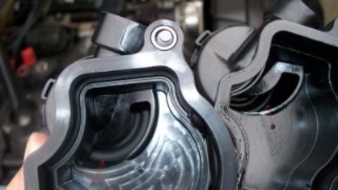 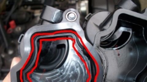 For the baffle, I'll go to Bed Bath and Beyond today in search of a perforated pan to cut out: they come in different shapes and sizes so I hope to find something that serves the purpose: https://www.google.com/search?q=perf...h=600#imgdii=_ Last edited by ZetaTre; 05-30-2014 at 05:29 PM.
|
|
#3
05-30-2014, 05:21 PM
|
|||
|
|||
|
PART 3
Allright fellas: here's the story of first prototype, currently installed in my car for testing. First the hardest part of the job: tampering the anti-tamper bolts. The clue that there was something going on first came by looking at the diagrams on RealOEM that didn't show the crankcase breather valve (from now on CCV) as a separate item for US cars; the ROW cars like the 30sd that is the base for our 35d had it as a separate item, but not ours. Here's the two diagrams side by side: left is the US 35d, while right is a ROW 30sd:   It turns out that the bolts that are labeled 10 in the ROW (and are missing in the US) are actually some Allen bolts with a pethagon socket in the head. Despite my fairly furnished tool box I didn't have such a socket but I wasn't going to stop: an old Allen wrench, the almighty Dremel, and a hammer and you can jam a socket in there and take them off. Other than those bolts the rest of the CCV system is precisely the same as the ROW which I confirmed comparing the p/n stamped on the parts. When putting it back together I used some Allen bolts I had there, but if you want to go ahead and used BMW bolts (which are kind of cool since they have a mechanism to trap the bolt in the sleeve so the don't fall out) the p/n is 11-12-7-803-813. Passed this hurdle, it's pretty much as planed with next step being cutting the various stages appropriately. First you'll need a template. To create one simply rub some of that nasty used diesel oil saturated with soot around the perimeter of the CCV and use it to stamp a template on piece of paper: 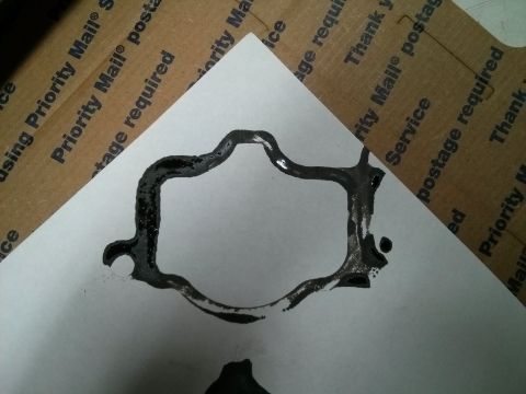 Once you got the template you're ready to cut. I didn't go with a fully on baffle, but still added a nice stainless steel mash inside the CCV: the purpose again is to hold the filter in place and create an air gap between the filter and the outlet. 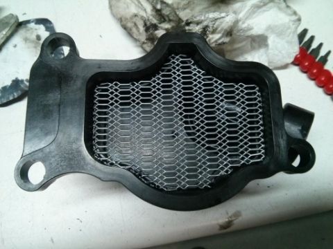 You then want to go ahead and do the same with filters. As I described in the previous post I used a staged approach, and actually went ahead with also Stage 3, which is using the media from the Mann Provent 200. Using a box cutter you can easily remove it from the assembly. You actually don't have to buy, like I did, the whole Provent, you can source the filter by itself. Here's a possible source: [LC-5001-X]Mann-Filter European CCV Element(SI - Industrial Heavy truck and Bus/Off-Highway ). 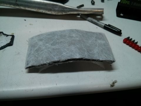 After cutting the two stripping pads you may want to wash them with some hot water to remove any loose particles. Here's how the stacked assembly looks like: 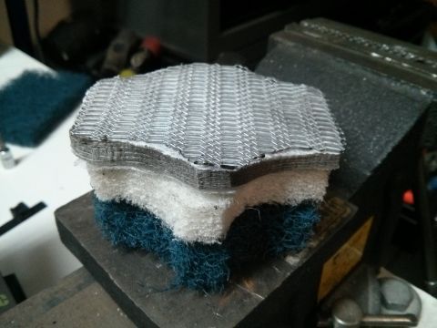 You then go ahead and pack the wire mash and the Provent media in the CCV... 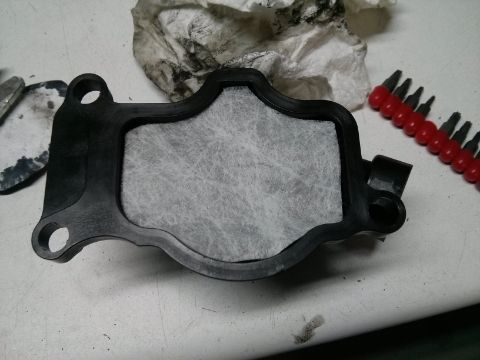 ...and the other two stages in the cavity in the valve cover 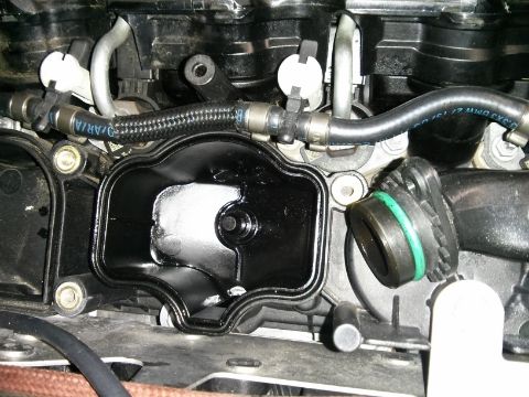 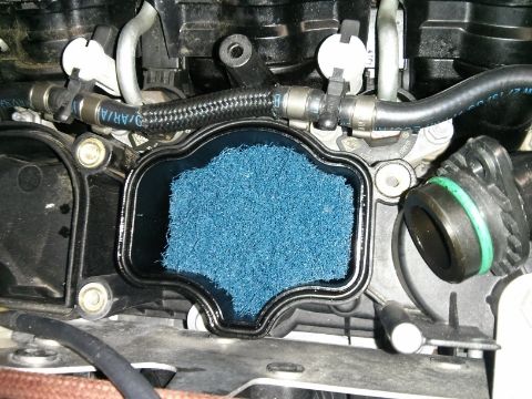 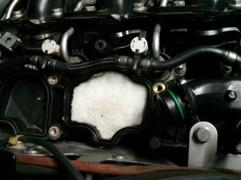 Now that you got everything installed, you can put it back together. -------------------------------------------- After putting it back together the car fired up just fine an has been running just fine: no differences whatsoever, odd noises, even checked several parameters and everything is within norm. The flow of gasses doesn't appear to be restricted in any way; if you compare the surface of the filter to the section of the passages is probably an order of magnitude different. Bottom line I don't expect this affect the performance in any way... But I guess time will be the judge. If I have time tonight or tomorrow morning I'll remove it and check for obvious signs of problems. Otherwise I'm gone for the weekend to the race track so the X5 will do some towing and I suspect by next weekend I'll probably have a good 1,000 miles on the setup. At that point I'll go ahead and remove it and check for integrity. Long term I think two indicators would tell me if this works or not: 1) I've noticed oiliness in the rubber hose going form the CCV duct to the intake, inside the intake itself and a little puddle of oil right in front of EGR throttle: we'll see what happens to either 2) I've gone though roughly 1 qt of oil every 7K miles: based on 1 I suspect that most if not all of it comes from the CCV so we'll see how things go over the next oil change There is one thing I want to bring up to everyone that I'll have no way to test: I don't know if the filter could cause issue below freezing. In particular moisture from the crankcase vapors could get trapped in the filter and freeze. This could clog it resulting in high pressure and a bunch of problems. I live in San Diego, car is always parked in the garage so for me that's not a problem. I wanted to bring this up so that you consider it. ------------------------------------ I guess the last thing is that I'll update this thread based on my results. Ciao!!!! Last edited by ZetaTre; 05-30-2014 at 05:33 PM.
|
|
#4
09-21-2014, 09:53 AM
|
||||
|
||||
|
Great initiative with this ZetaTre. You're like me; always trying to improve on existing methods. Any updates on this? I definitely want to do this but live in Wisconsin and the freezing temps may create issues as you mention.
Thanks for your effort here!
__________________
Life is not a journey to the grave with the intention of arriving safely in a pretty and well-preserved body, but rather to skid in broadside, thoroughly used up, totally worn out and loudly proclaiming: "WOW! WHAT A RIDE!!" 2007 M6 2018 Chevy 2500HD Diesel Alaskan Edition 2011 X5 35d 1972 Chevy K20 4X4 1972 Ford F-600 1959 Chevy Viking 60 Dump Truck 2015 CanAm Outlander XT 1000
|
|
#5
01-07-2015, 07:08 PM
|
|||
|
|||
|
The original design was not effective enough so, as some may have read on the other board, I actually went ahead and installed a Mann+Hummel ProVent 200 separator.
I now have about 15,000 miles on the setup and I'm extremely pleased with the results. The oil in the intake has completely disappeared and the oil level in the sump has not declined. I went through a few iteration and testing to ensure that the crankcase would not pressurize under any driving conditions. I have also modified the dipstick tube to make it the return line for the filtered oil and make the system completely closed loop. I'm now refining the design of the takeoff plate: someone I know was able to scan the profile of the original CCV and machine the plate on CNC machine for a perfect design. I also found an aluminum elbow and I'll have it TIG weld to the plate for a clean and professional design. The plate currently mounted on the car is the proof of concept I made from a 1/4" aluminum plate cut to shape using a jig saw and soldering a copper elbow: it works but it's not pretty and the solder is fragile and I already broke it once while replacing the hose. Also the hoses I originally used for the long term testing was a duct made of thermoplastic rubber: it turned out that it is either too porous or not resistant to the oil because the one running from the valve cover to the filter (which carries unfiltered fumes) have developed a film of oil on the outside. I went back to the Gates rubber hoses I had originally but have identified some corrugated nylon conduits that I may try if the rubber hoses don't work. Some of the key takeaways of the project: REROUTING THE BRAKE BOOSTER LINE This was necessary to make enough room for the Provent 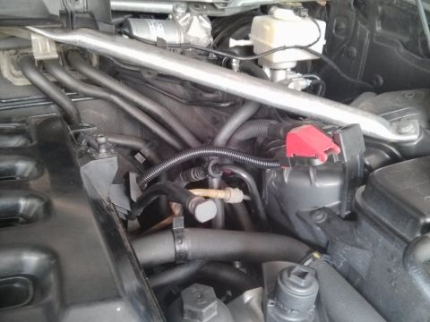 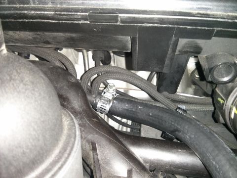 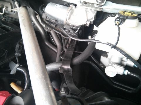 MAKING THE BRACKET TO SUPPORT THE PROVENT Now that the brake booster line is out of the way I removed the bracket that was holding it... 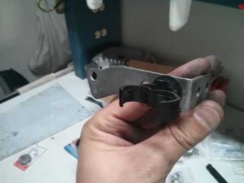 and used it as a template to make a bracket that would go in the same location to hold the ProVent 200 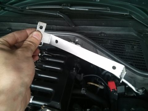 See if it fits... 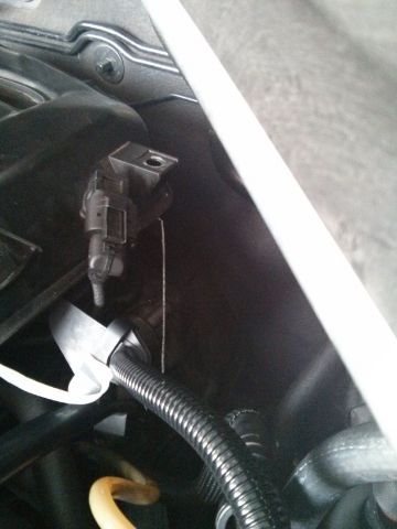 And install the ProVent 200... 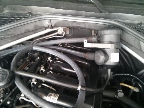 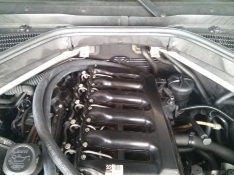
__________________

Last edited by ZetaTre; 01-07-2015 at 07:34 PM.
|
|
#6
01-07-2015, 07:18 PM
|
|||
|
|||
|
MAKING THE "PROOF OF CONCEPT" TAKEOFF PLATE
This is currently being reworked with a plate made on a CNC and an aluminum elbow TIG welded to it. 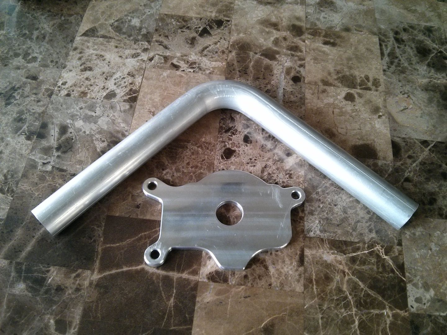 Here's the original plate I made and which is currently mounted on the car. Because the ProVent 200 has a built in valve regulating the amount of vacuum, there is no need for the original one. Once removed, I used it a template to draw an outline on a 1/4" aluminum plate... 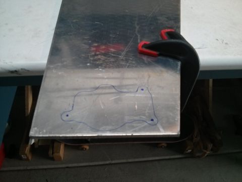 After some jigsaw and Dremmel, let's see how it fits... 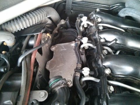 I then went ahead and soldered a 1" copper elbow to it: 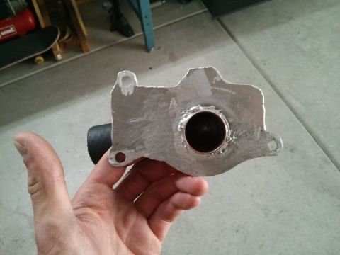 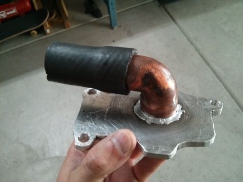 MEASURING CRANKCASE PRESSURE AND ADAPTING THE PROVENT To measure crankcase pressure I used a homemade gauge I used in the past to sync the TBs of the Ducati 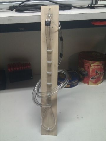 It is a simple vynil tube shaped in a U over a yard stick. You put some water in, one side goes into the dipstick tube and the other is open to the atmosphere. 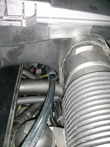 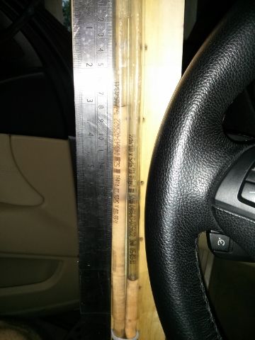 After driving around for a bit it turned out that under high load and high RPM the turbos would create to high of a depression in the intake. This would cause the valve on the ProVent to close and the crankcase to build up pressure. The solution was to disassemble the valve on the ProVent and add a few holes. I started with 5 which turned out to be too many so I patched 2. 3 holes result in normal reading under any driving conditions. 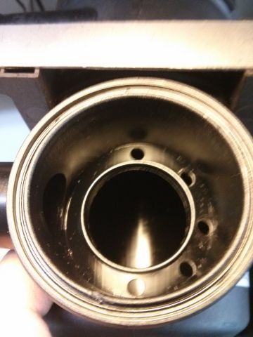
__________________
Last edited by ZetaTre; 03-04-2015 at 04:15 PM.
|
|
#7
01-07-2015, 07:25 PM
|
|||
|
|||
|
MEASURING EFFECTIVENESS
For a period of time, I actually drove around with a valve on the oil drain that I would regularly drain to collect the filtered oil [there's nothing coming out of that valve, it's just some odd light effect...]. I had it tucked it away behind one of the plastic covers. 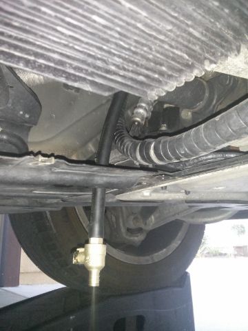 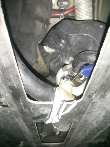 I knew the system was working remarkably well when after 1,864 miles I collected this much oil. 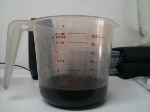 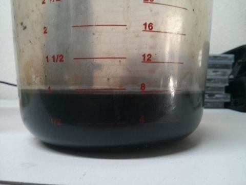 MODIFY THE DIPSTICK TUBE TO ADD A RETURN LINE This made the system maintenance free and allowed the oil to drain back to the sump. I was able to find be the perfect tee to make a saddle on the oil dipstick guide to drain the oil: Shop Apollo 1-in x 1-in x 1/2-in Barb Fitting at Lowes.com 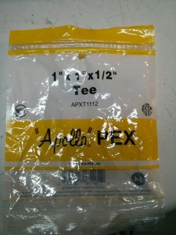 The tee is 1" x 1" x 1/2" Using a jig saw I cut lenghtwise the 1" section; with some epoxy and some clamps to add strenght I attached it to the dipstick guide and once the epoxy cured I drilled through the 1/2" nipple to open the drain. Here's the final product: 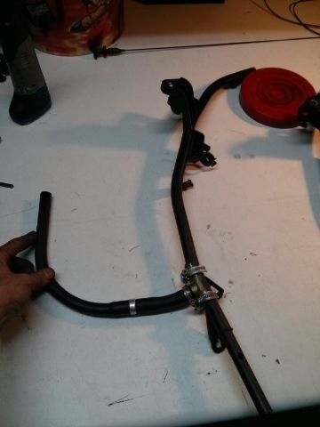 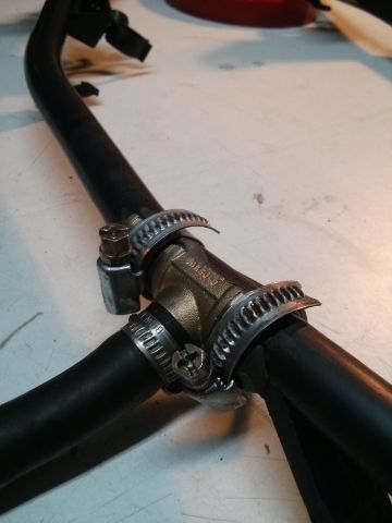 What you see there along the rubber drain is a check valve that allows oil to drain but doesn't allow fumes to travel up the drain. 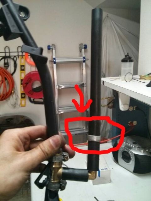 After noticing that the hose would tend to kink, I added a elbow for a better turn.
__________________
Last edited by ZetaTre; 01-07-2015 at 07:37 PM.
|
|
#8
01-07-2015, 10:48 PM
|
||||
|
||||
|
Very nice write-up. This is something that I have wanted to do, Thank you for information. I'm going to work on a parts list.
__________________
8/2011 X5 xDrive35d Sport, Black Sapphire Metallic, Black Nevada Leather, Fine Burr Walnut Trim 2/2001 M5, Jet Black, Exclusive Complete Black Walk Nappa Point Heritage Leather, Black Cubic Trim
|
|
#9
01-09-2015, 02:19 PM
|
|||
|
|||
|
Quote:
You can get the p/n from the ProVent catalog here: https://www.mann-hummel.com/fileadmi...nt_en_2013.pdf
__________________
|
|
#10
01-09-2015, 08:49 PM
|
||||
|
||||
|
Quote:
__________________
8/2011 X5 xDrive35d Sport, Black Sapphire Metallic, Black Nevada Leather, Fine Burr Walnut Trim 2/2001 M5, Jet Black, Exclusive Complete Black Walk Nappa Point Heritage Leather, Black Cubic Trim
|
|
| Bookmarks |
|
|
|
|


 Linear Mode


