
|
|
|
|
||||||||||
| Xoutpost server transfer and maintenance is occurring.... |
| Xoutpost is currently undergoing a planned server migration.... stay tuned for new developments.... sincerely, the management |
 |
|
|
LinkBack | Thread Tools | Display Modes |
|
#1
 12-22-2005, 02:40 PM
|
|||
|
|||
|
Modifying the Ice>Link cable for fewer connections (DSP systems)
Here is my modification of the Ice>Link cable that reduces the number of connections and simplifies installation in DSP equipped (required) cars. Picture 1: The original cable supplied by Tom.  Picture 2: Close up of the 3 and 6 pin connectors. 3 pin is data and power, while 6 pin is analog audio. There is an in-line fuse on the brown (+12V).  Picture 3: Better view of the 6 pin analog audio connector. Black jumper bridges ground for both left and right channels.  Picture 4: Cut off the 6 pin connector. This will be discarded.  Picture 5: Strip of the outer insulation from the twin coaxial analog audio cables.  Picture 6: Twist the shield wires into leads. These are the negatives for the analog audio.  Picture 7: Tin the leads. I used a silver based solder.  Picture 8: Put short lengths of heat shrink tubing over the existing wire insulation. This builds the cables diameter making better anchor points for the RCA connectors.  Picture 9: Some good quality, inexpensive Neutrik RCA connectors.  Picture 10: Solder on the RCAs. Don't forget to put the RCA barrels over wire before soldering.  Picture 11: Finished twin RCA connectors in place of single 6 pin BMW proprietary connector.  Picture 12: Carefully remove black wire from power 3 pin connector to solder negative wire of DSP power cable. Reinsert pin into connector when done soldering.  Picture 13: Solder positive (black with white strip) cable to brown wire fuse terminal (after the fuse). Reinsert the fuse terminal pin when finished.  Picture 14: Bundle the wires together.  Picture 15: Behold the finished cable.  Picture 16: All finished. Power for DSP module is pulled from CD changer power, and it's fused.  Picture 17: Harness connects to the vehicle at two points: 3 pin power/data connector and coaxial digital audio connector on amplifier.  Picture 18: Test the system with your iPod in the boot. 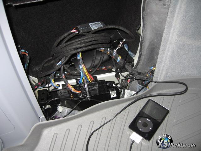 Next challenge is getting the cable routed to the center console. 
|
| Sponsored Links | |
|
|
|
|
#6
12-23-2005, 02:17 AM
|
||||
|
||||
|
Good Job!

__________________
Tom G. | european auto source (eas) email: [email protected] web: www.europeanautosource.com tel 866.669.0705 | ca: 714.369.8524 x22 | fax: 714.908.1796  Twitter | Flikr | Facebook | YouTube
|
|
#7
09-19-2015, 01:09 PM
|
|||
|
|||
|
Cable
That first original cable, for some unknown reason it's missing in my bmw e46 with build in navi. Does anyone knows where I can buy that cd changer cable with the 3-and 6-pin connection? I need it to make an aux input...
|
|
| Bookmarks |
|
|
|
|


 Linear Mode


