|
||||||||
| Xoutpost server transfer and maintenance is occurring.... |
| Xoutpost is currently undergoing a planned server migration.... stay tuned for new developments.... sincerely, the management |
|
|
LinkBack | Thread Tools | Display Modes |
|
#1
|
|||
|
|||
|
GM 5L40-E teardown
I recently acquired a ‘failed’ GM 5L40-E transmission, which is used in the early E53 3.0 litre M57 diesel models, just so I could repair it for fun. The one I bought is actually from an L322 Range Rover but it’s identical to the E53 version except for slight differences in the output shaft arrangement (NV225 vs NV125 transfer box).
My particular transmission was reported as having lost reverse gear. It should be said that the 5L40-E transmission is notorious for failing at between 80,000 and 100,000 miles in the Range Rover. I assume it’s a similar story for the X5 and consequently the 5L40-E (A5S360R) was swapped out for the slightly higher torque capacity 5L50-E (A5S390R). Anyway, here we go with the teardown.... Starting at the bottom, first off is the sump pan (20-off 10mm A/F bolts) and the metal & rubber gasket :  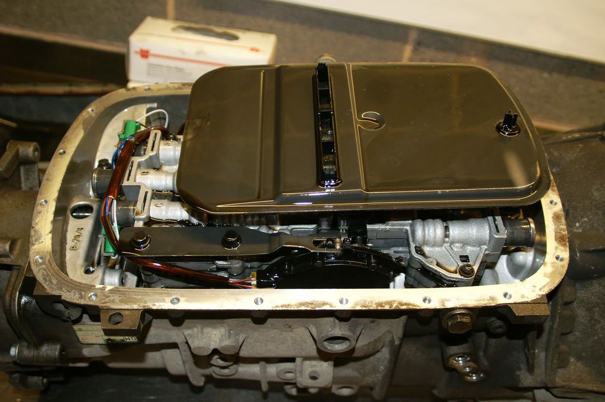 As soon as the sump pan came off it was clear that something was amiss - it looked like there’d been an explosion in a glitter factory! Everything was covered in fine metallic debris : 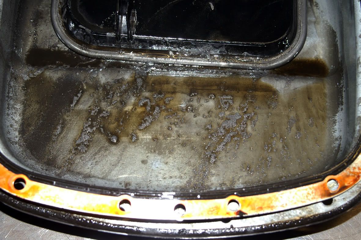 The filter comes off easily (just pull) 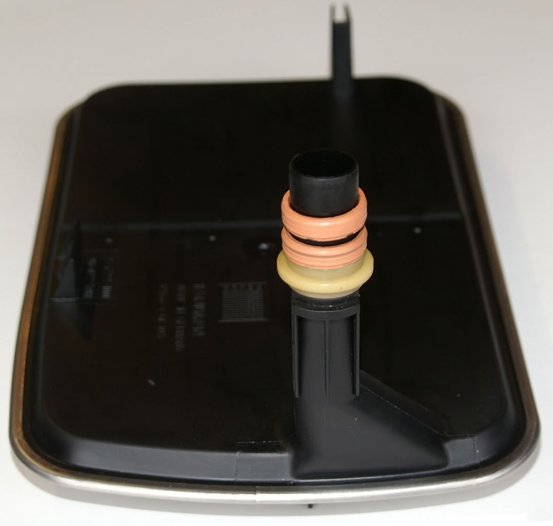 Note that the filter has a spacer and two seals. Like with the ZF boxes the ‘correct’ filter is made by Filtran in Germany (the German border is only a few yards away from where the GM transmissions are built in Strasbourg, France). The wiring harness comes out next : 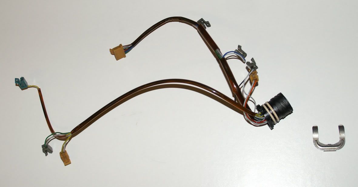 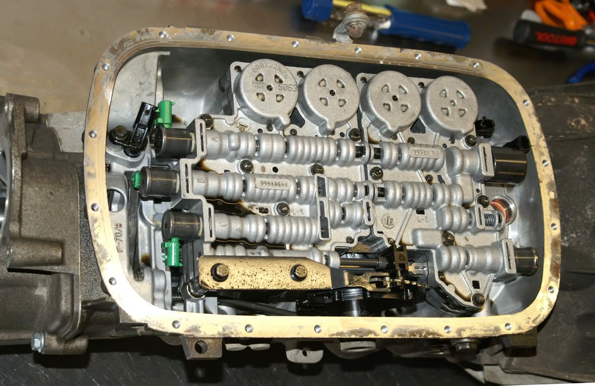 …followed by the valve block assembly. This is retained by nine screws – one with a 10mm A/F head and the remainder requiring a Torx E8 socket 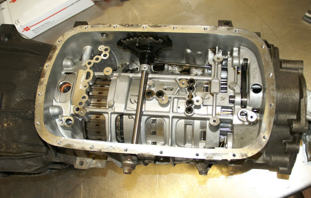 Interesting to see that GM put the inhibitor (or XYZ) switch inside the transmission rather than on the outside like ZF. Here's the valve block assembly from underneath : 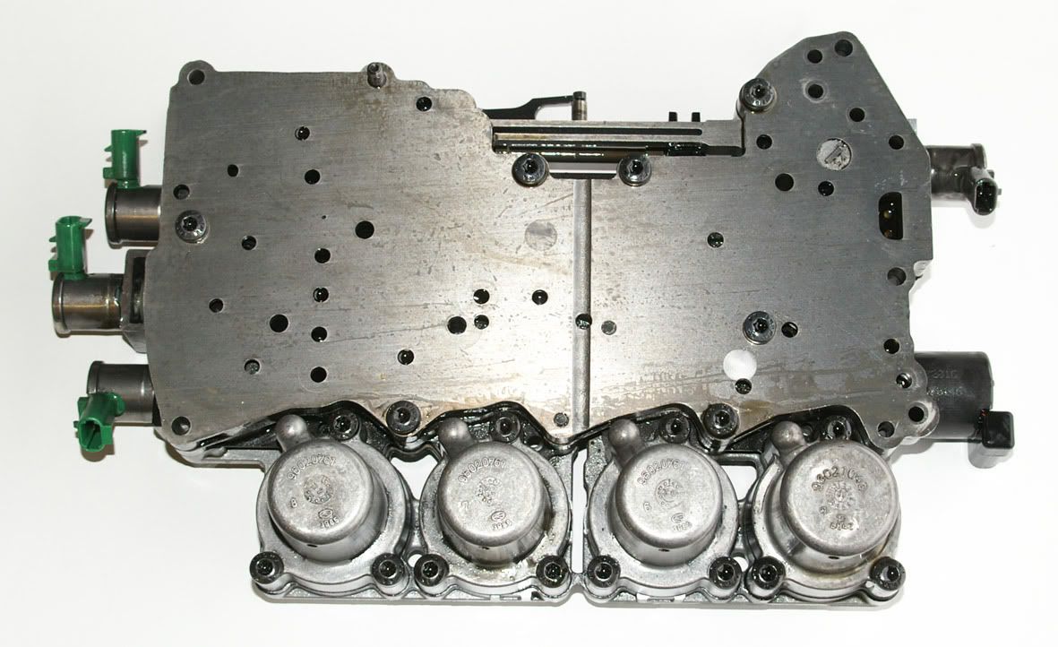 The five solenoids can clearly be seen as well as the four accumulators : 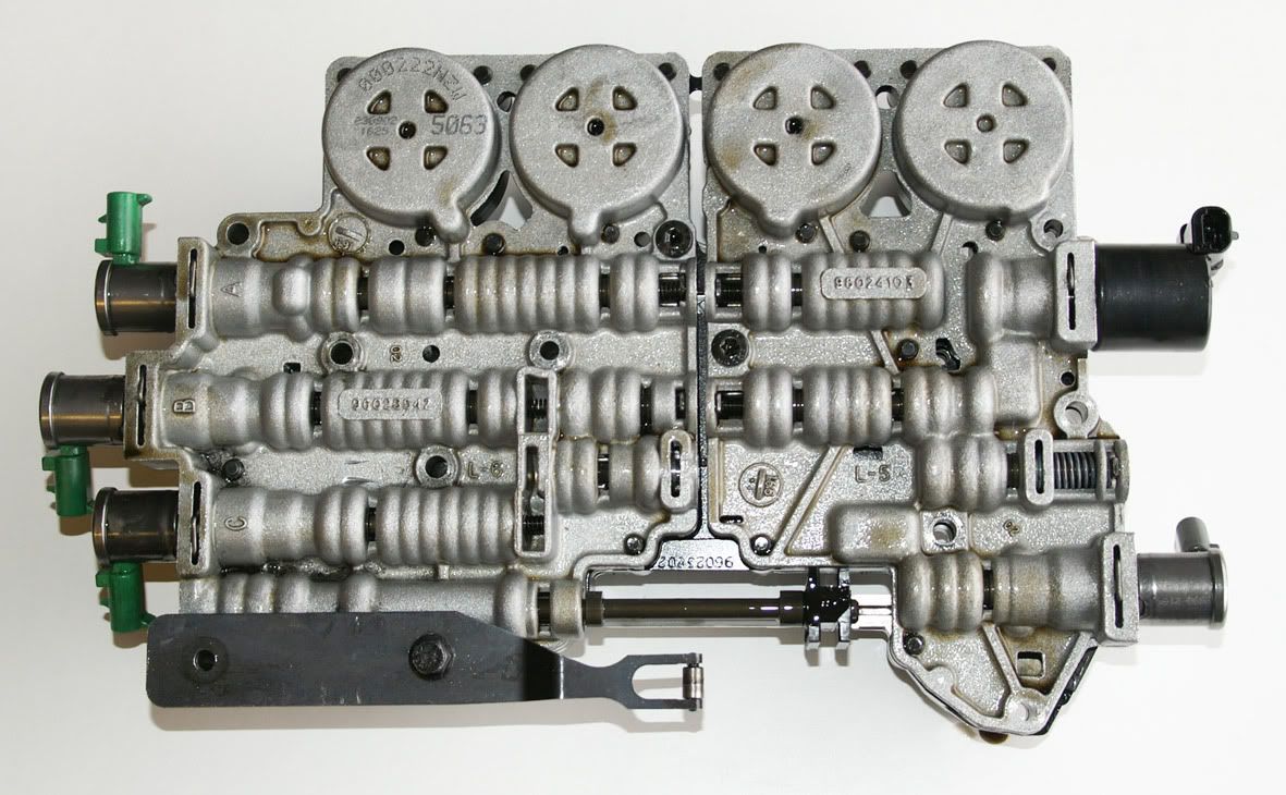 The three (identical) solenoids with the green connectors are the shift solenoids for the 1-2, 2-3 & 4-5 shifts (labelled A, B & C respectively in the casting). The similar sized solenoid at the other end of the block assembly, with the grey connector, operates the torque converter lock-up clutch. The remaining (large) solenoid is the pressure control solenoid whose job it is to adjust the transmission’s line pressure. I did a quick check of all five solenoids’ winding resistances and all were to spec. (at 20 deg. C. these should be : Shift solenoids = 15 to 17 Ohms, TCC solenoid = 10.0 to 11.5 Ohms and pressure control solenoid = 3.5 to 4.6 Ohms) The two speed sensors can then be removed (each held in with a single screw) : 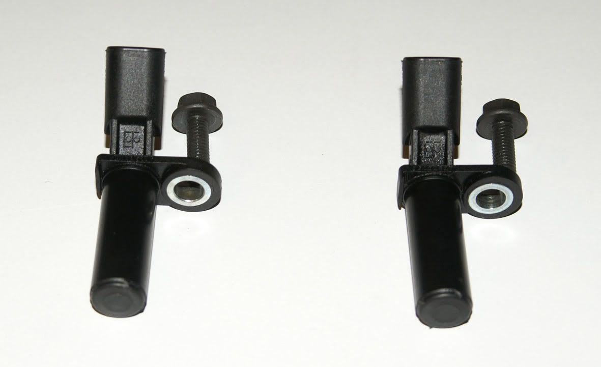 The sensors should have a resistance between 325 and 485 Ohms at 20 deg. C. Mine measured 387 and 389 Ohms. The jump tubes that feed fluid from the valve block to the clutches in the casing can then be removed (they're held together by metal straps) : 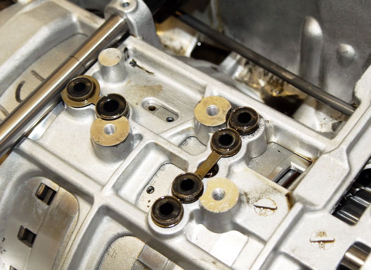 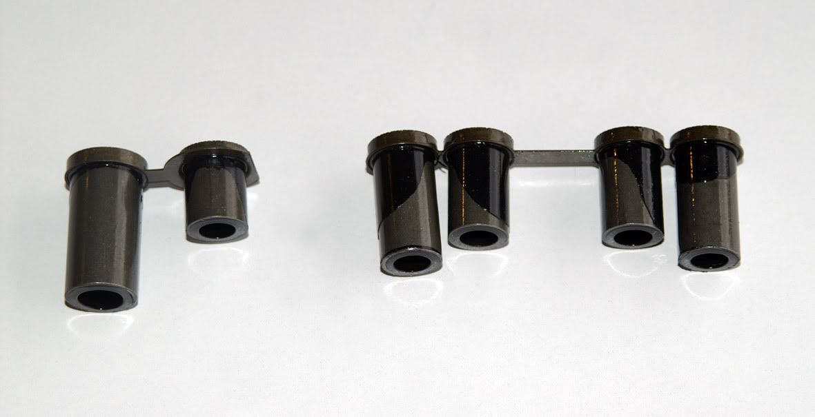 Okay, moving around to the front of the transmission now …… Just before removing the bellhousing I removed the torque converter turbine shaft O-ring : 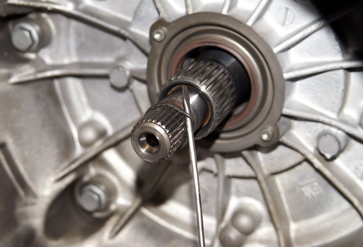 Then the seven 13mm A/F bolts which secure the bellhousing to the maincase follow : 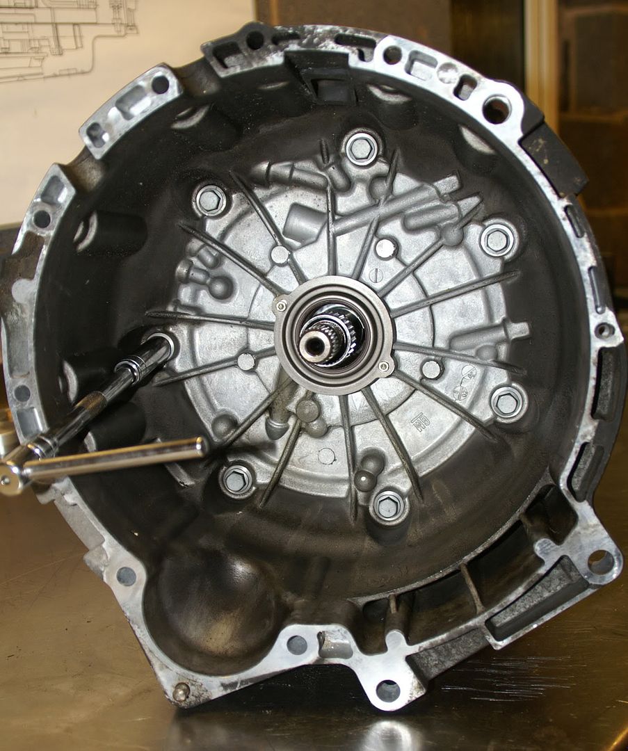 The bellhousing can then be drawn off. The oil pump cover assembly is bolted to the back of the bellhousing :  The running gear can now be extracted : 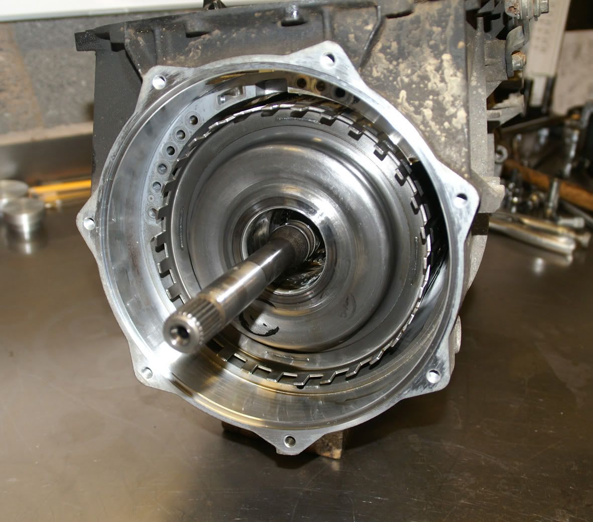 first the direct and reverse clutch assembly : 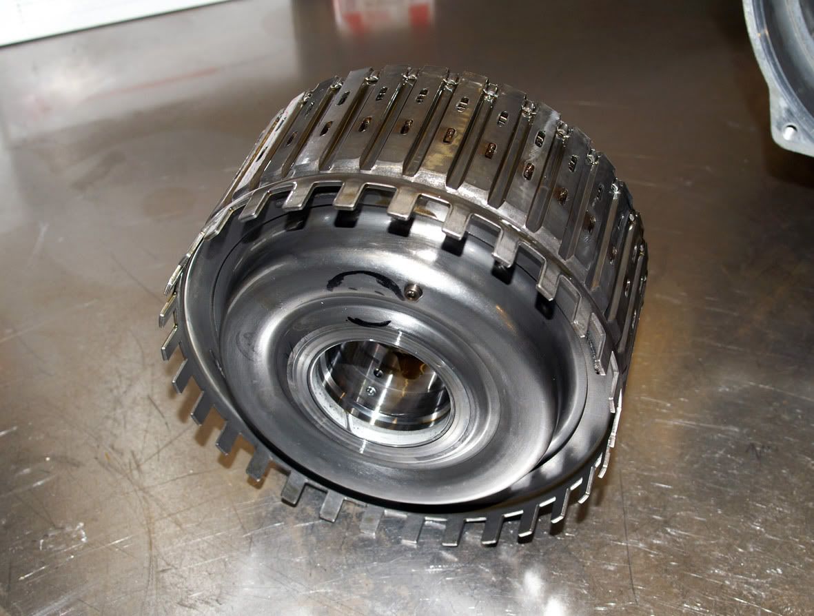 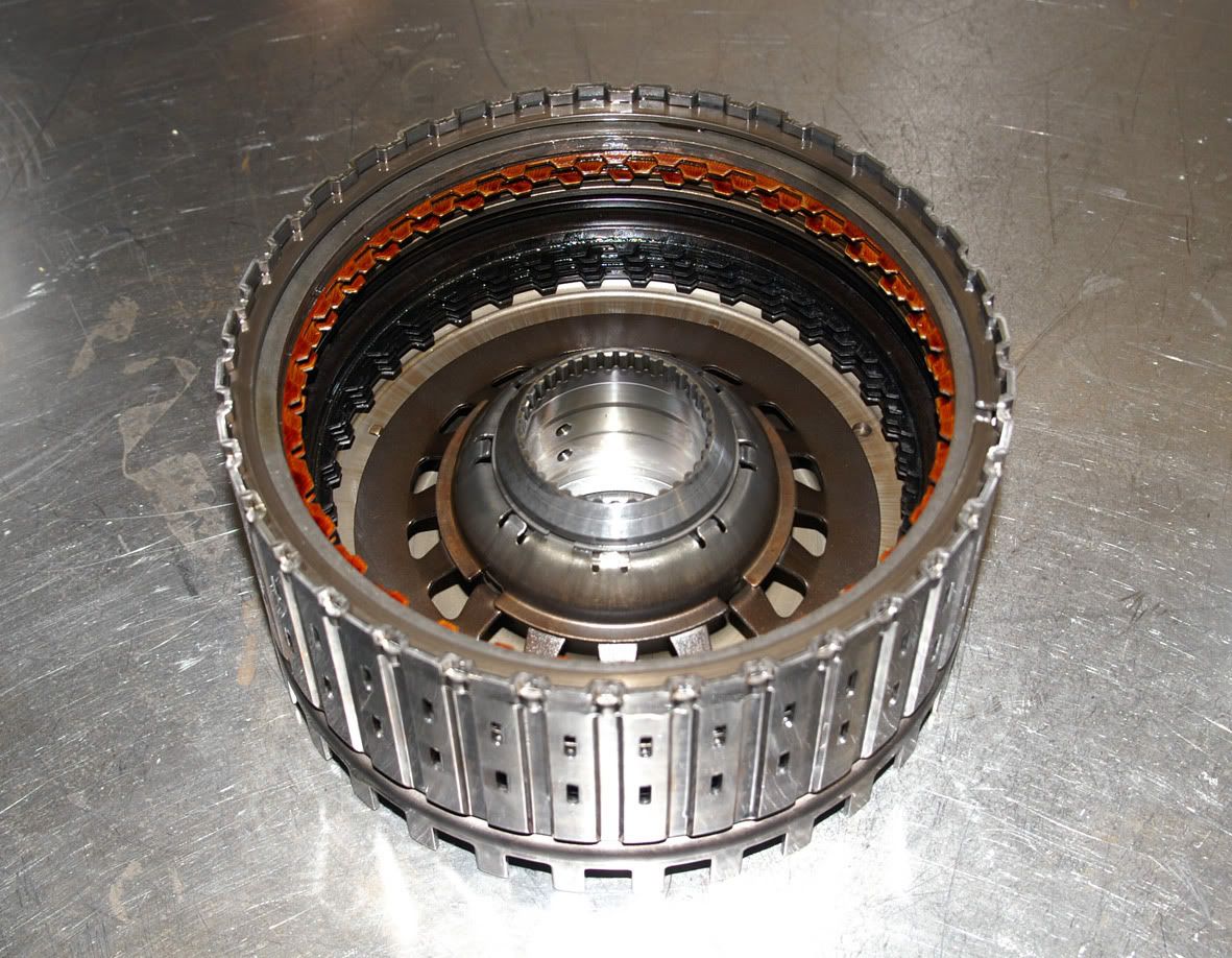 followed by the forward and coast clutch assembly (attached to the input shaft) : 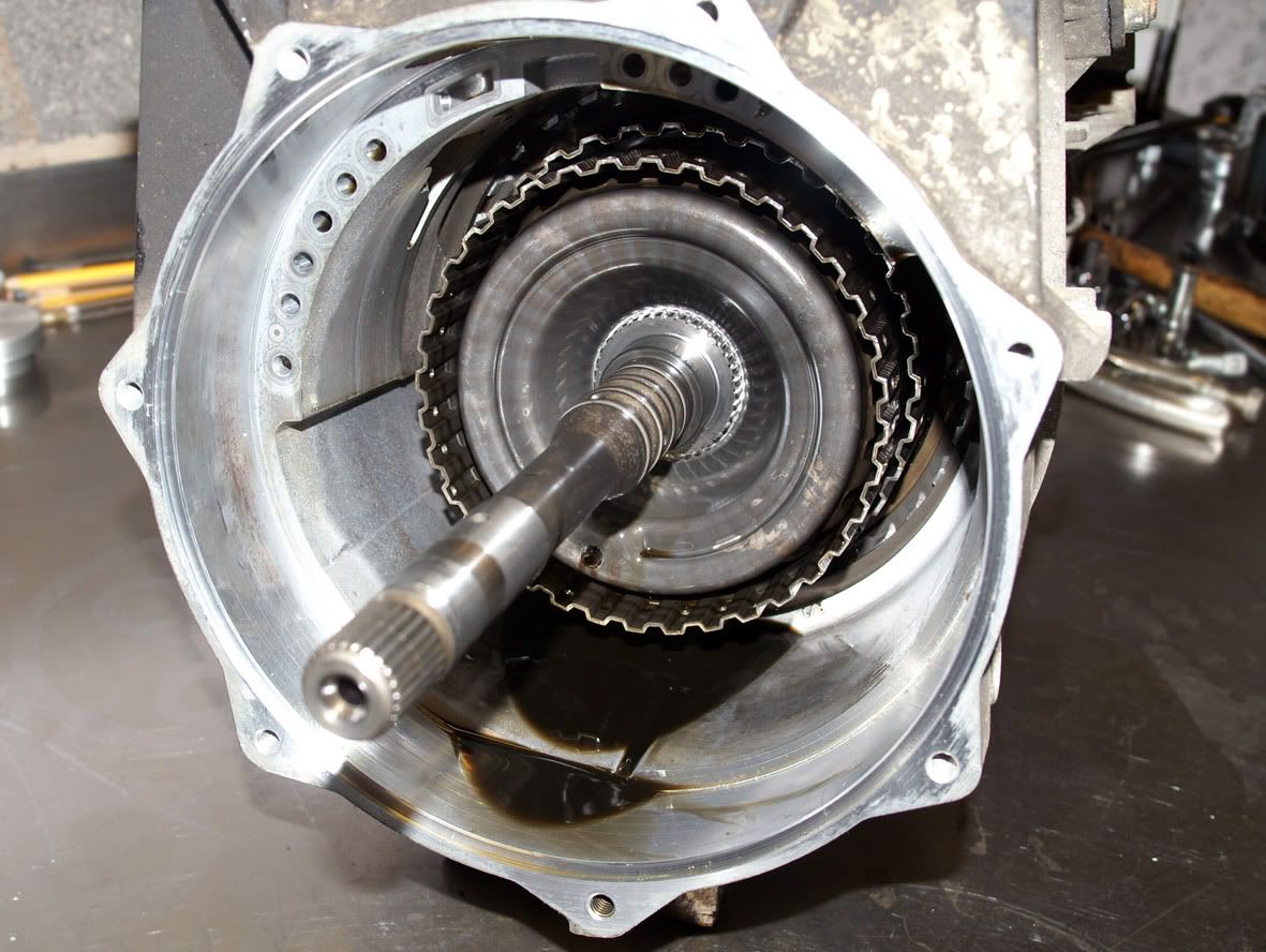 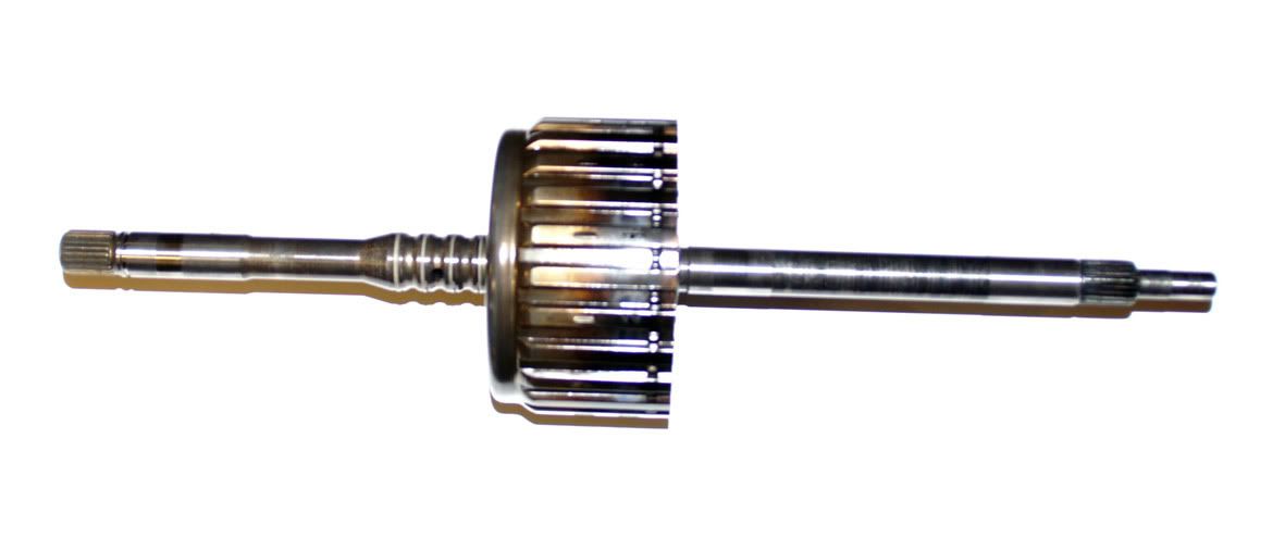 Hmmm, something wrong here! The input sun gear shaft and forward clutch sprag assembly comes with it and doesn’t want to part company with the forward and coast clutch assembly :  and clearly something has been getting a bit hot! With some effort I finally extract the input sun gear shaft and the forward clutch hub/sprag assembly has also obviously been getting very hot : 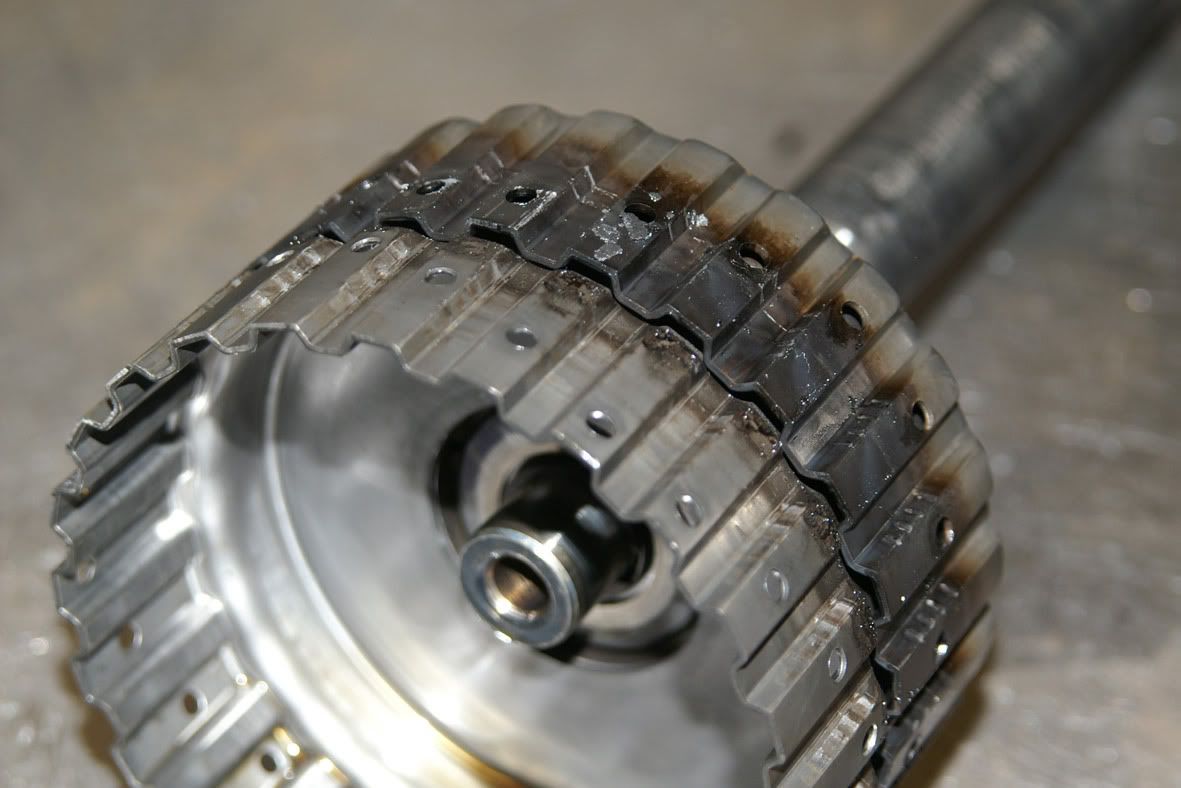 Removing the plates from the forward clutch : 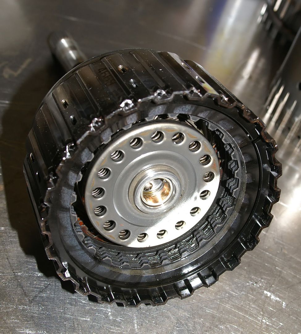 and, well, they are toast : 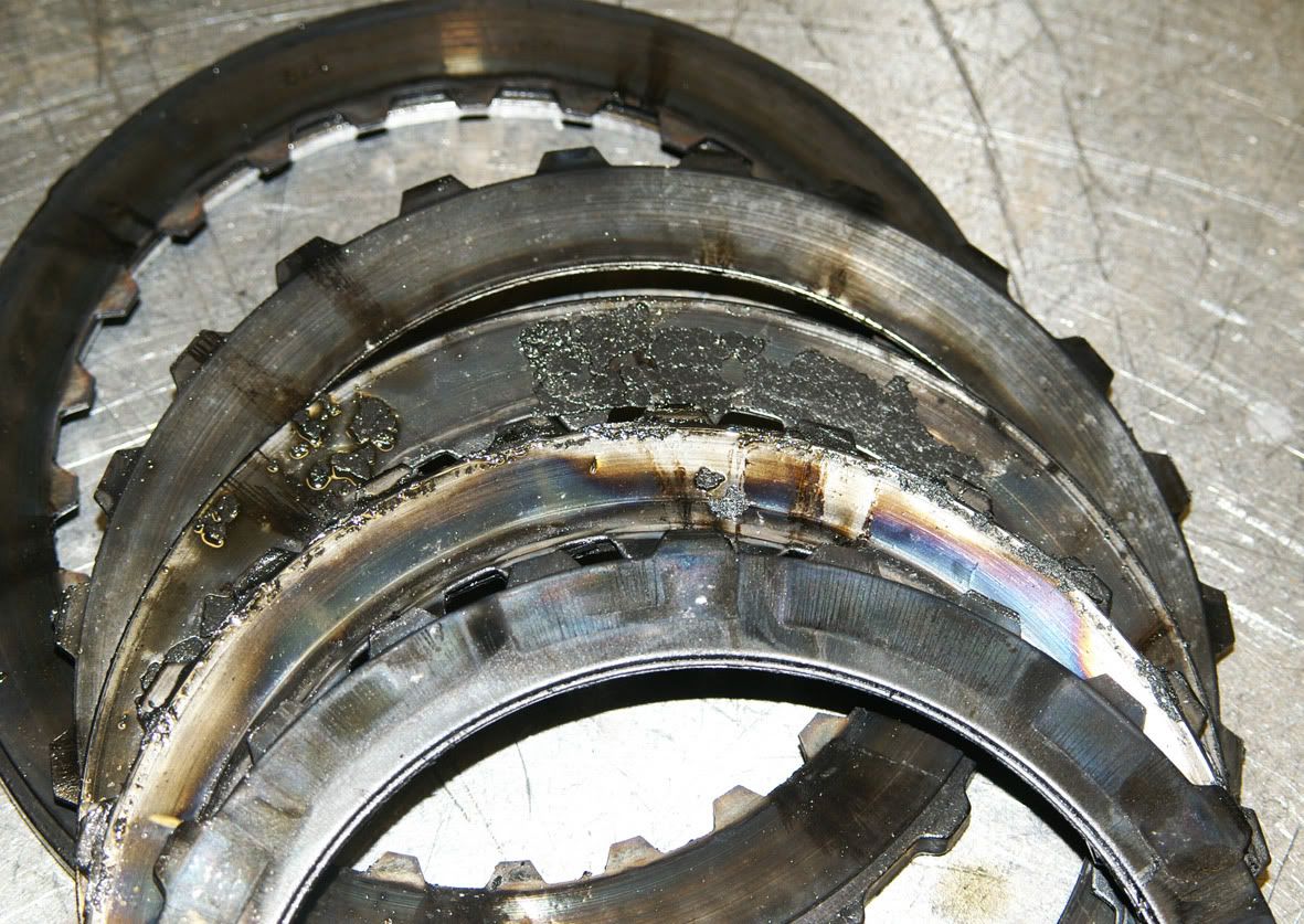 There’s nothing left of the friction material and several of the plates have friction welded themselves together. Next out is the direct clutch hub & shaft assembly : 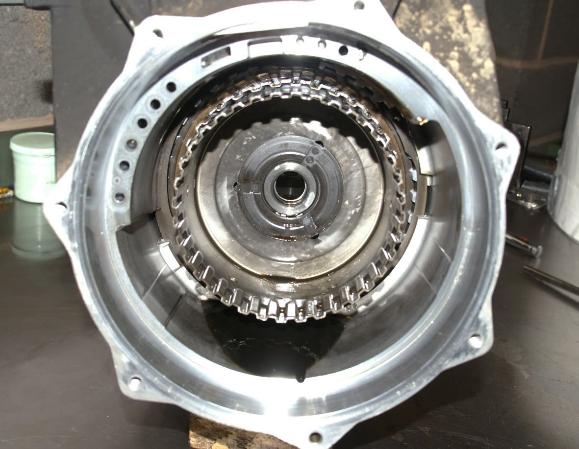 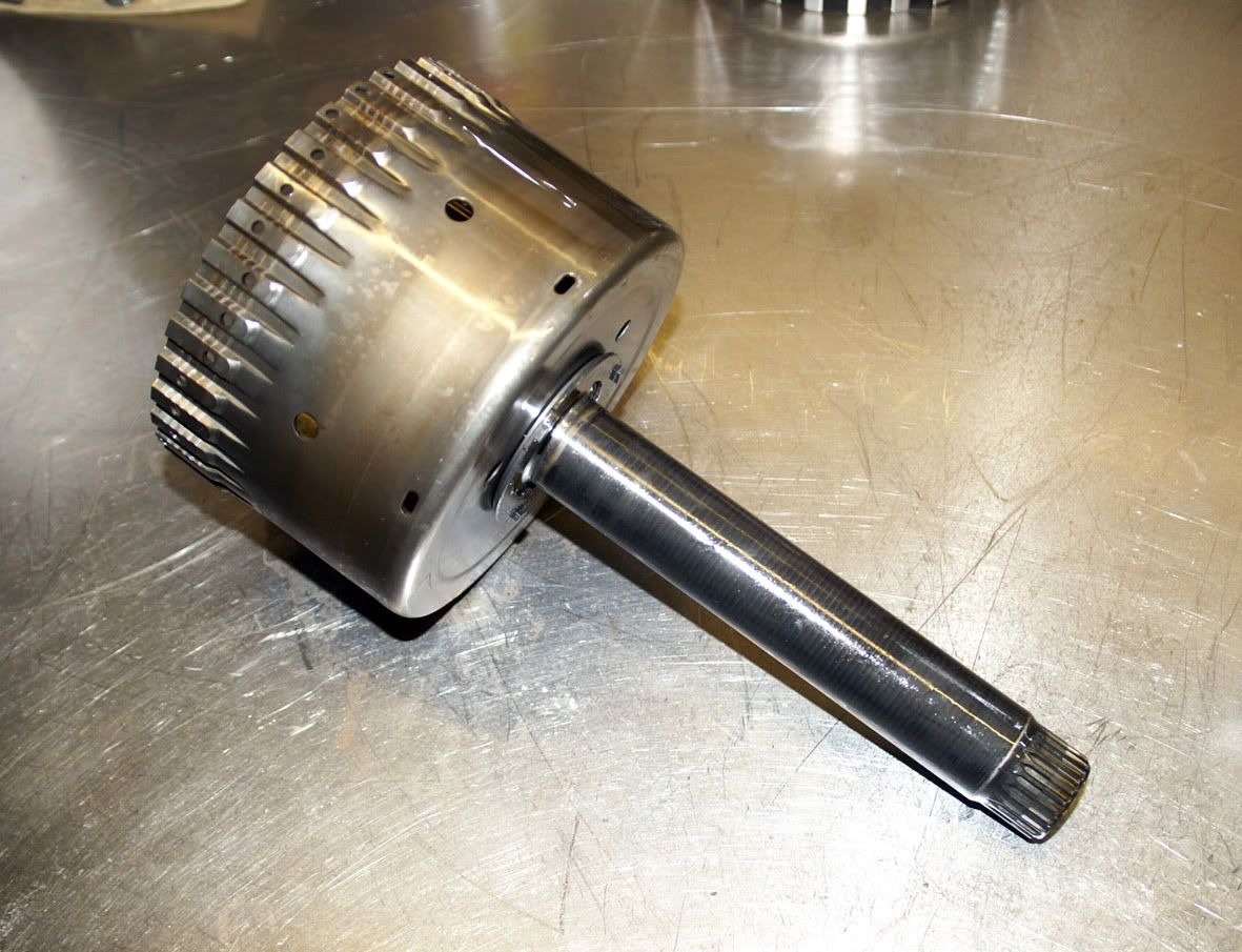 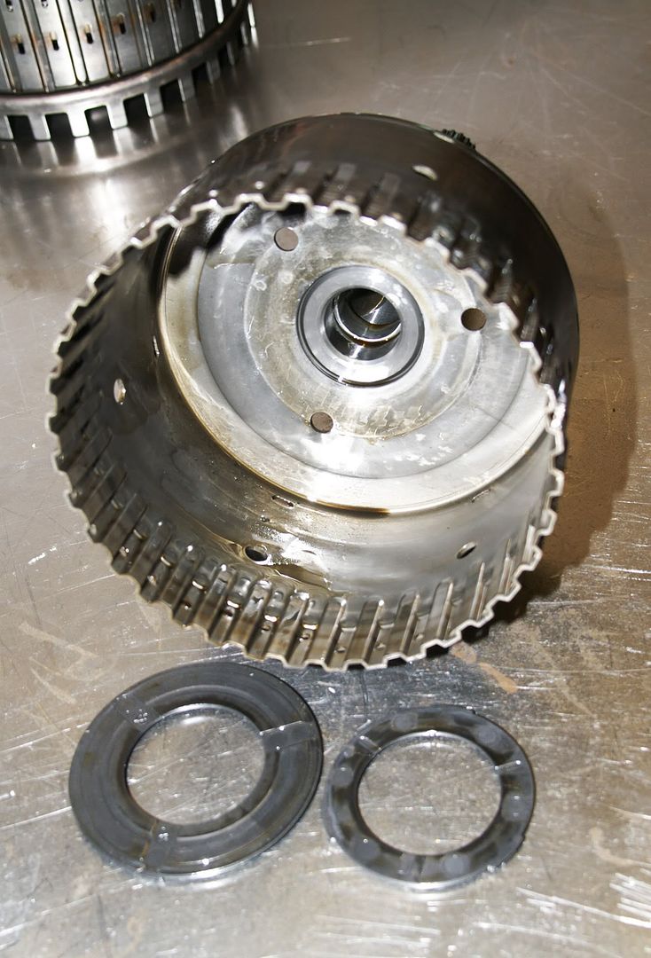 and then the overdrive and reverse clutch hub which has the intermediate clutch sprag assembly attached : 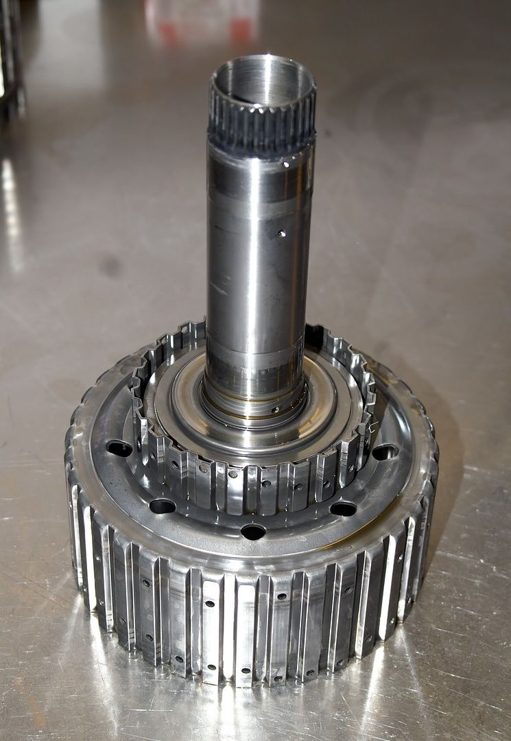 The next stage involves the removal of this huge circlip - which I’ve highlighted in red for clarity : 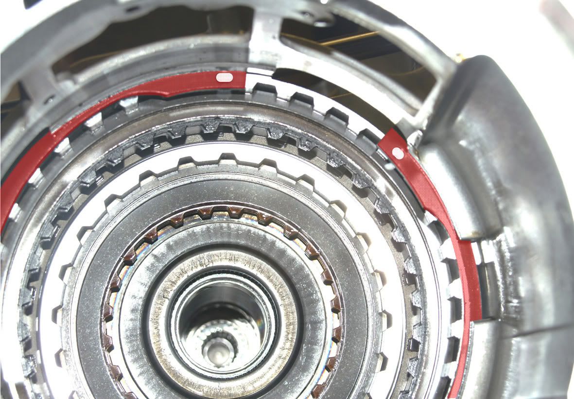 This requires a seriously large pair of circlip pliers 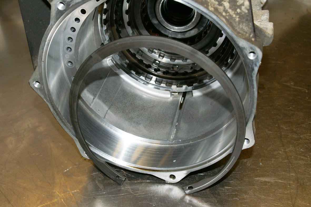 The retainer ring is selective i.e. it’s available in different thicknesses to cater for the particular tolerance stack up. The intermediate & overdrive clutch assembly then pulls out : 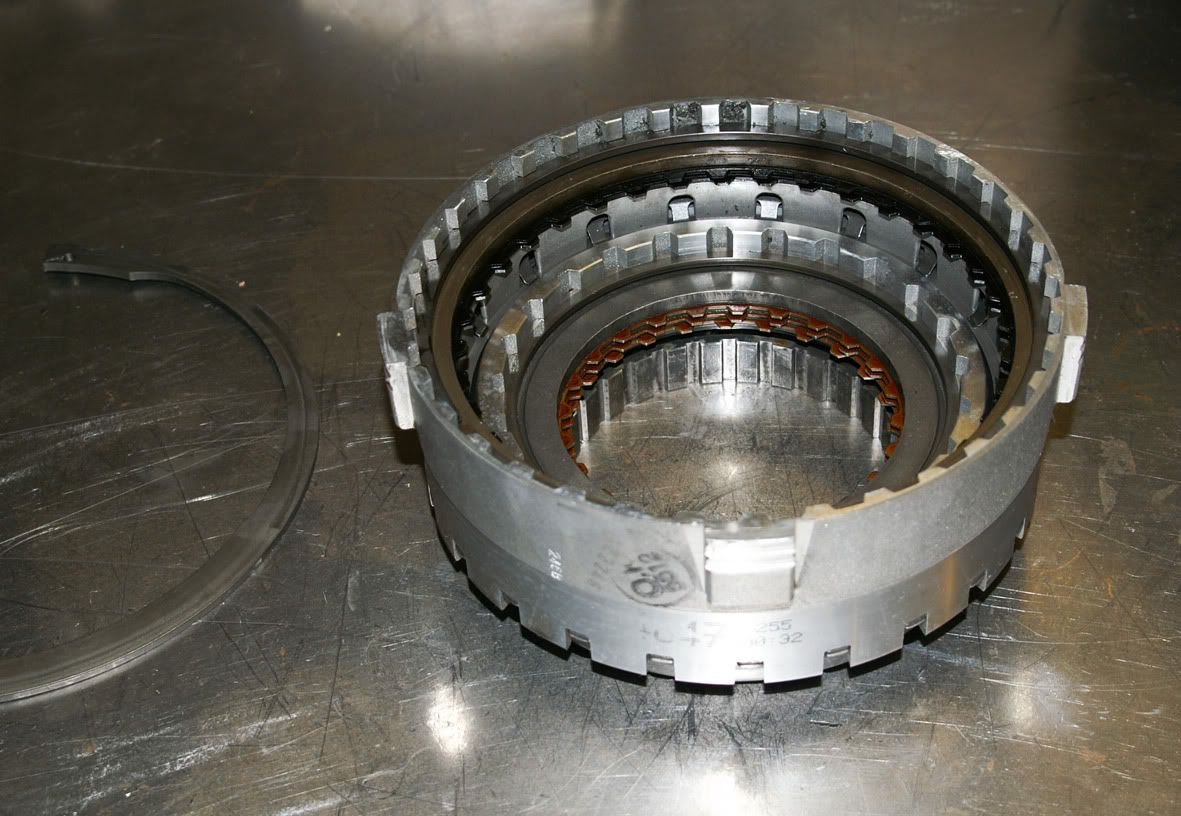 followed by the low clutch sprag assembly and its thrust washer : 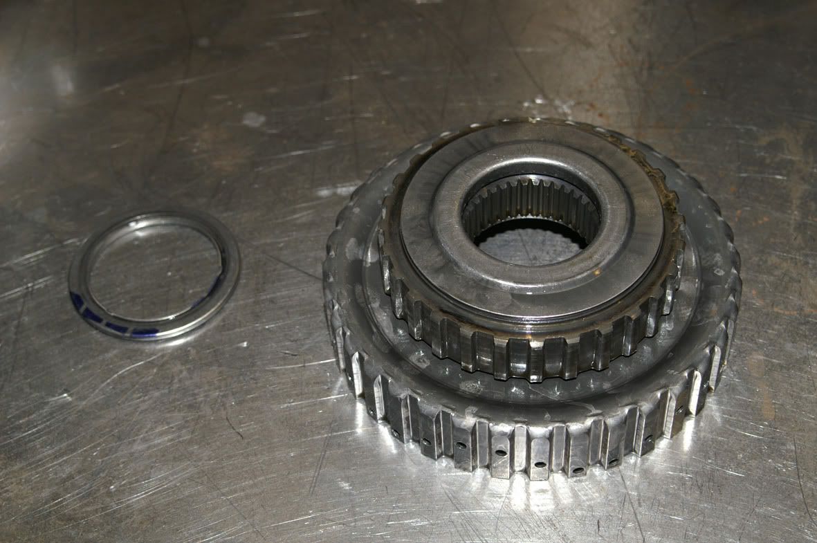 The centre support assembly can then be extracted from the casing : 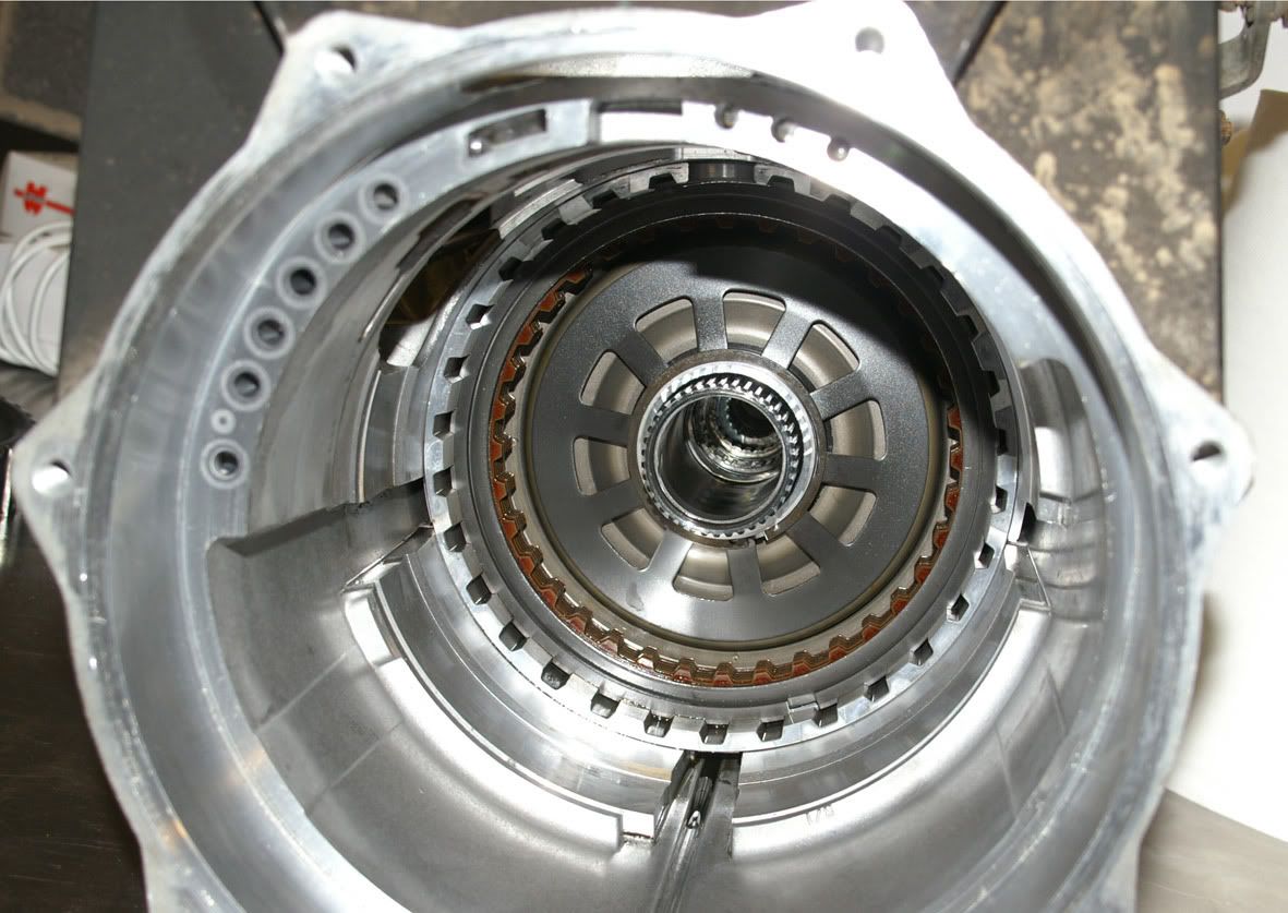 This centre support assembly includes the low/reverse clutch, second clutch and second coast clutch 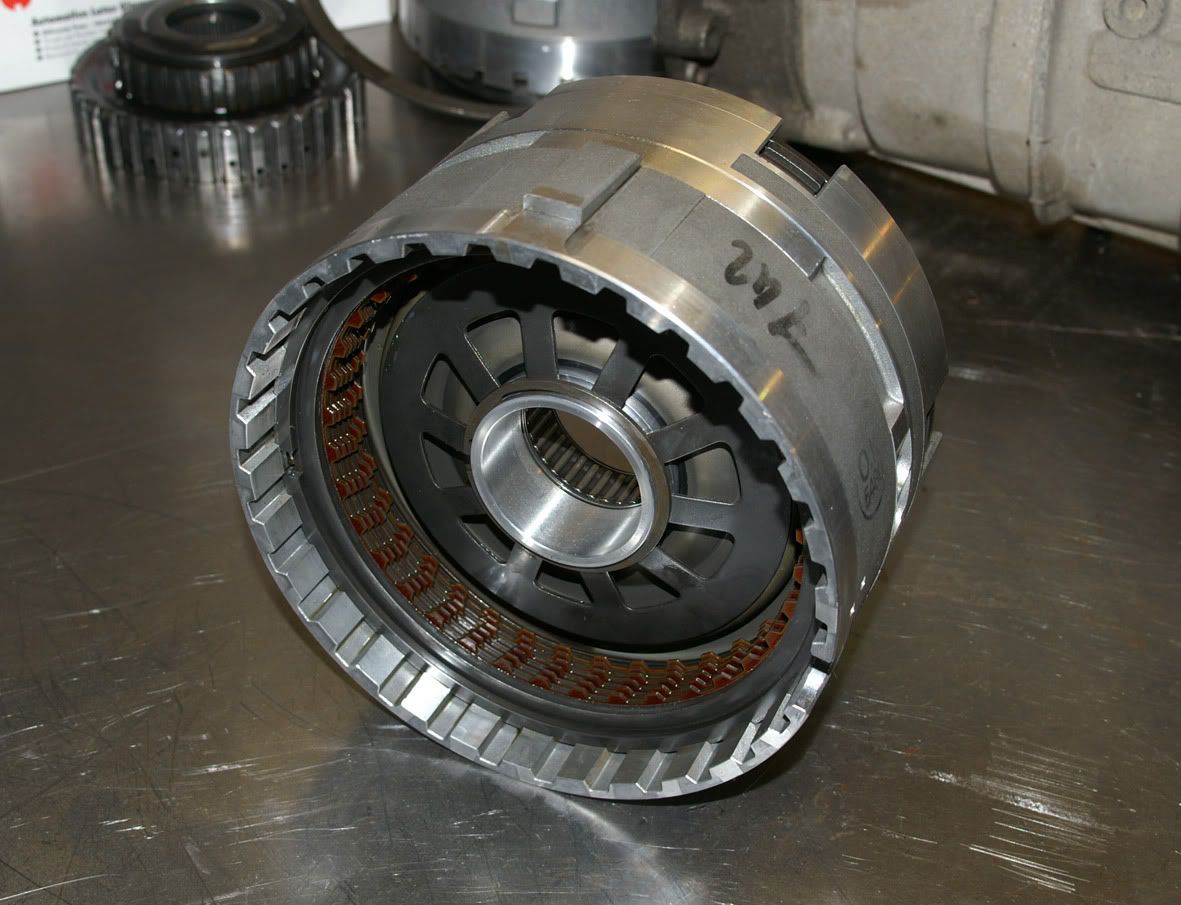 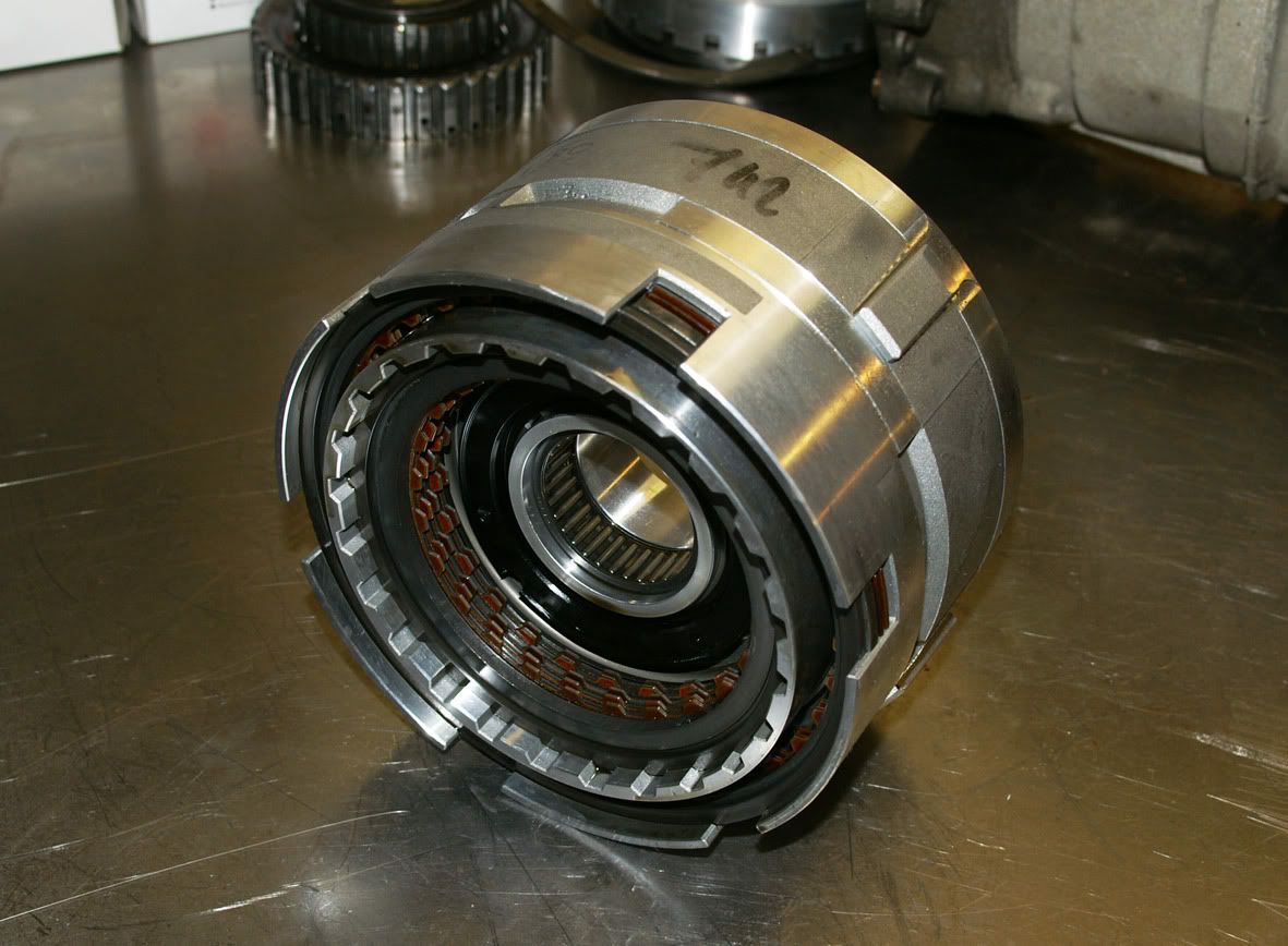 Then the planetary carrier assembly can be removed : 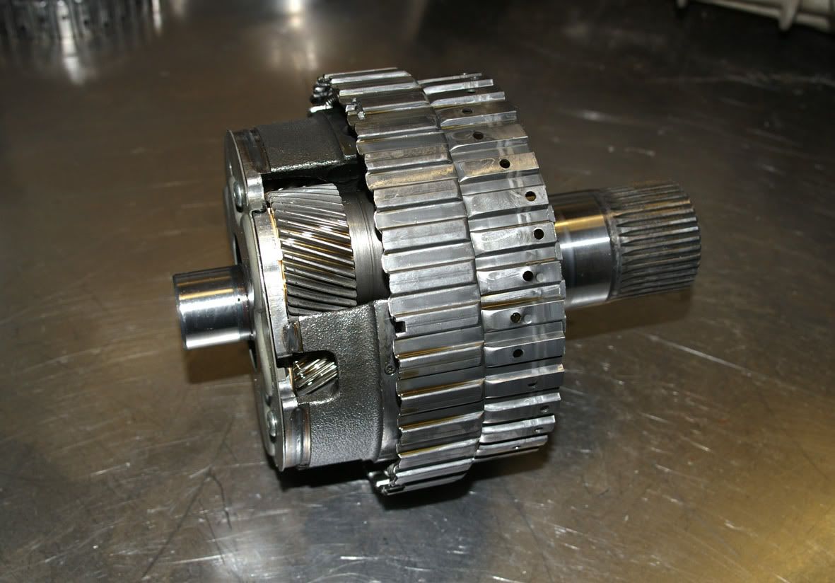 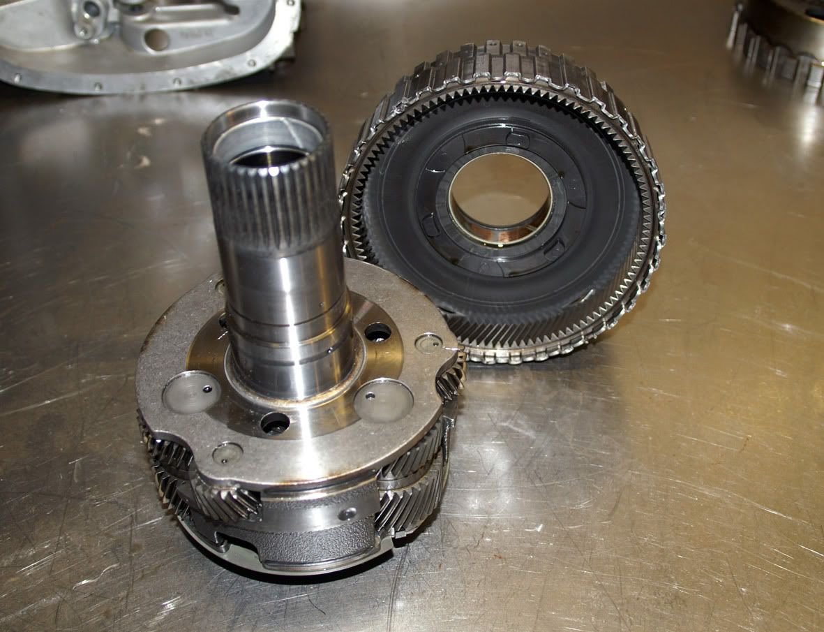 Leaving the rear internal gear/output shaft in the casing (you can see the park lock teeth around the outside of the internal gear) 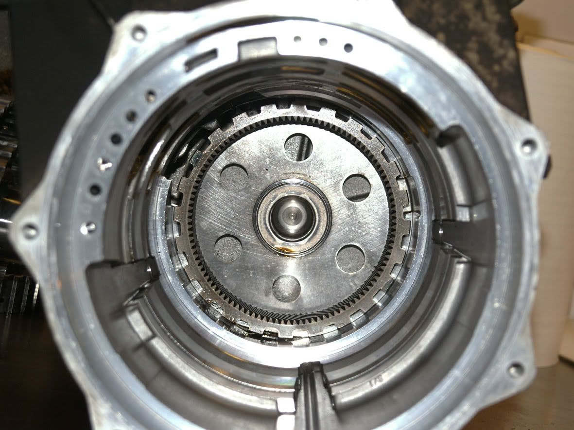 Now switching attention to the rear of the transmission..... 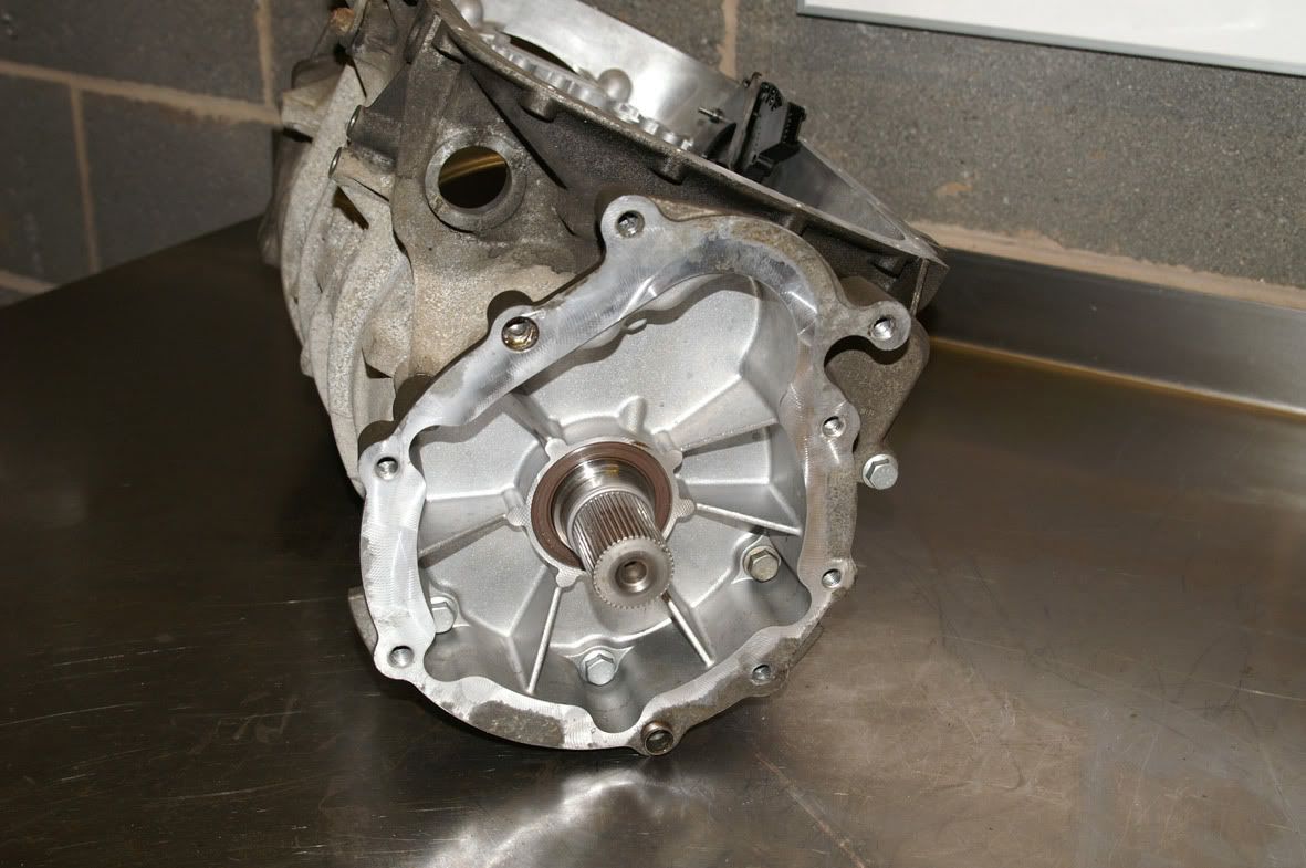 The rear casing is removed (7-off M13 A/F bolts) : 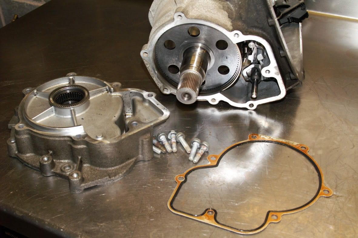 to gain access to the output shaft assembly : 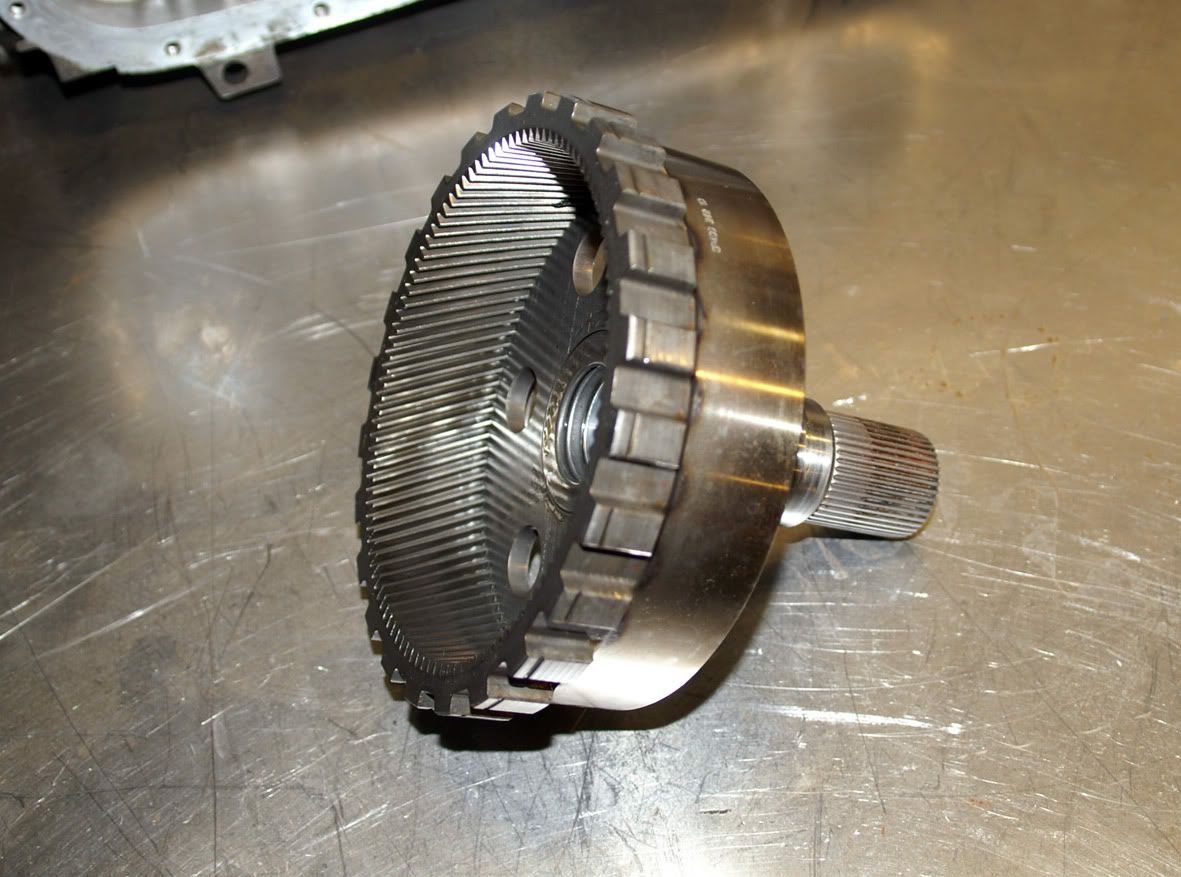 and the park lock engagement mechanism : 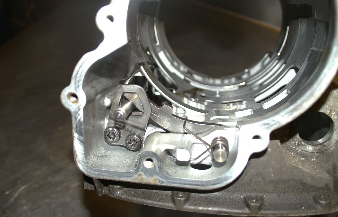 which just leaves the selector shaft assembly : 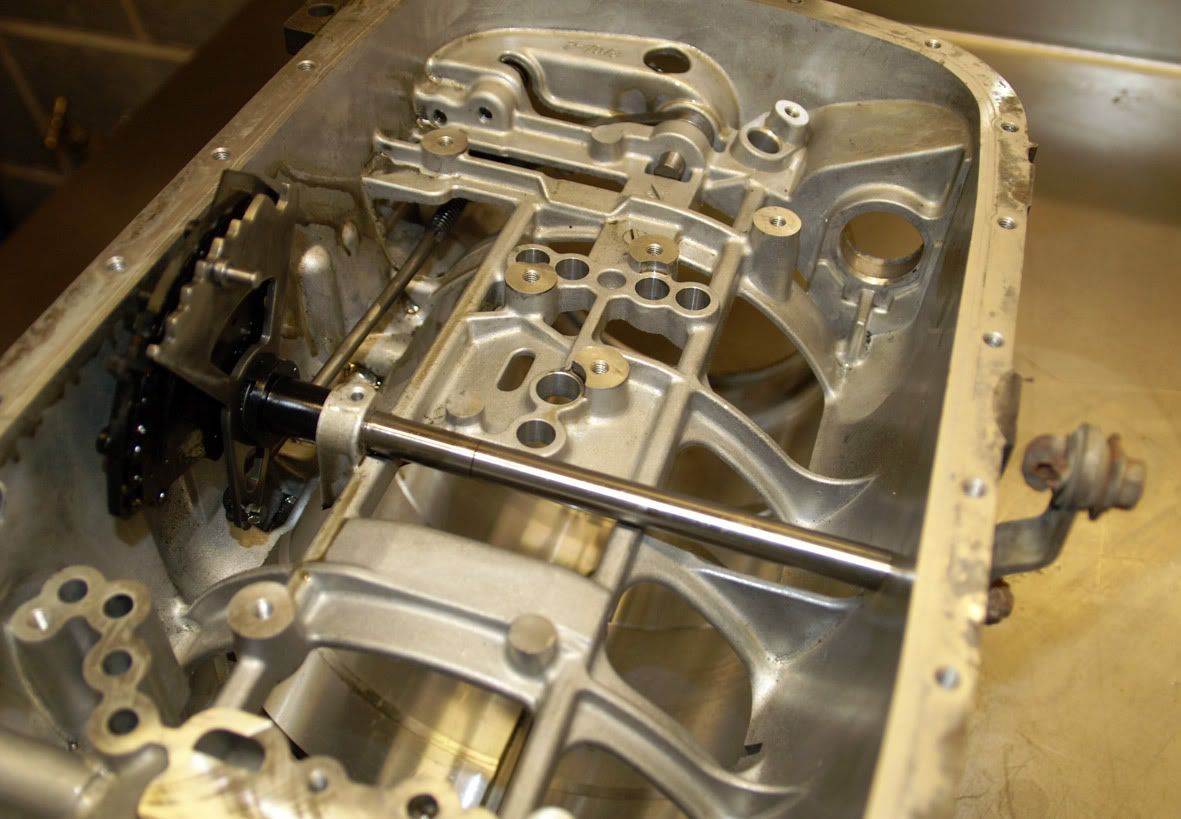 So having removed these last few components : 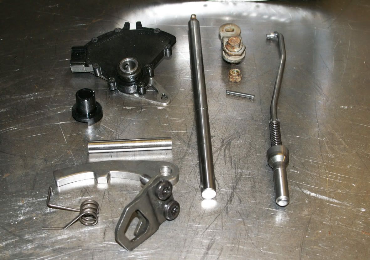 finally leaves an empty casing : 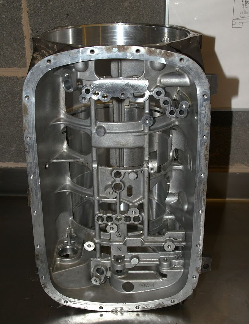 Regarding all the metallic debris that was found inside the transmission, clearly the failed clutch plates will have contributed but they can’t have been solely responsible for the huge quantity of debris discovered so I needed to dig a bit deeper. Here’s the torque converter with the weld, which holds the two halves of its casing together, removed : 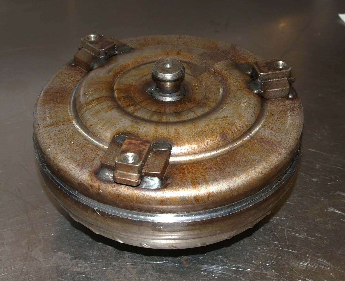 Lifting off the engine-side half of the casing reveals the torque converter lock-up clutch : 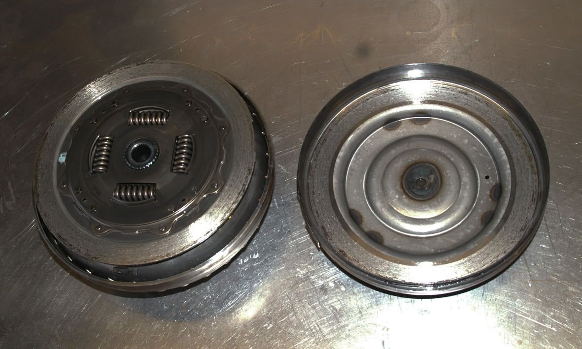 and I could immediately see that the clutch lining had disappeared completely allowing metal-to-metal contact : 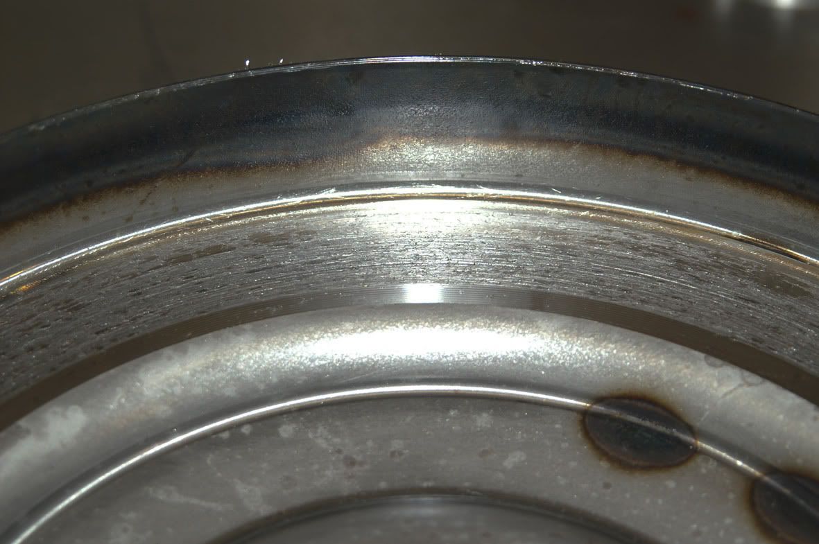 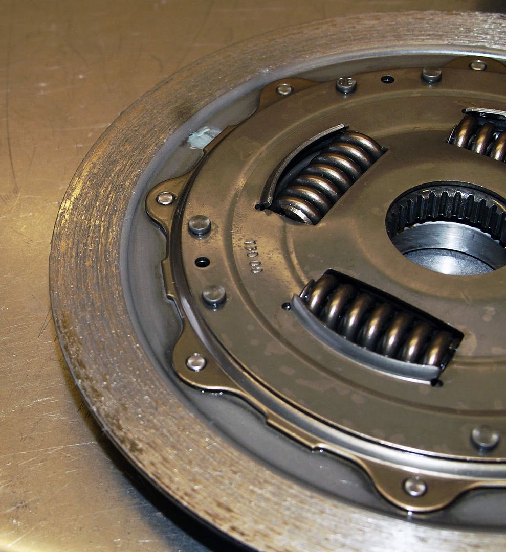 which is presumably where the majority of the metallic debris has come from. Lifting off the lock-up clutch assembly reveals the turbine : 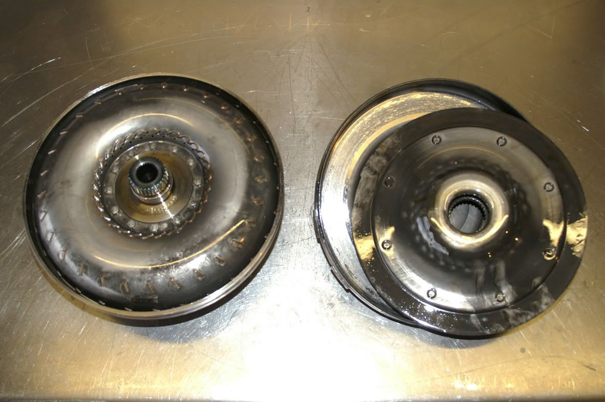 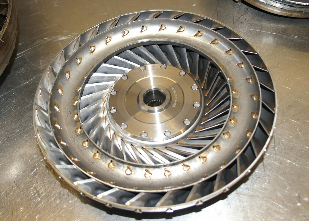 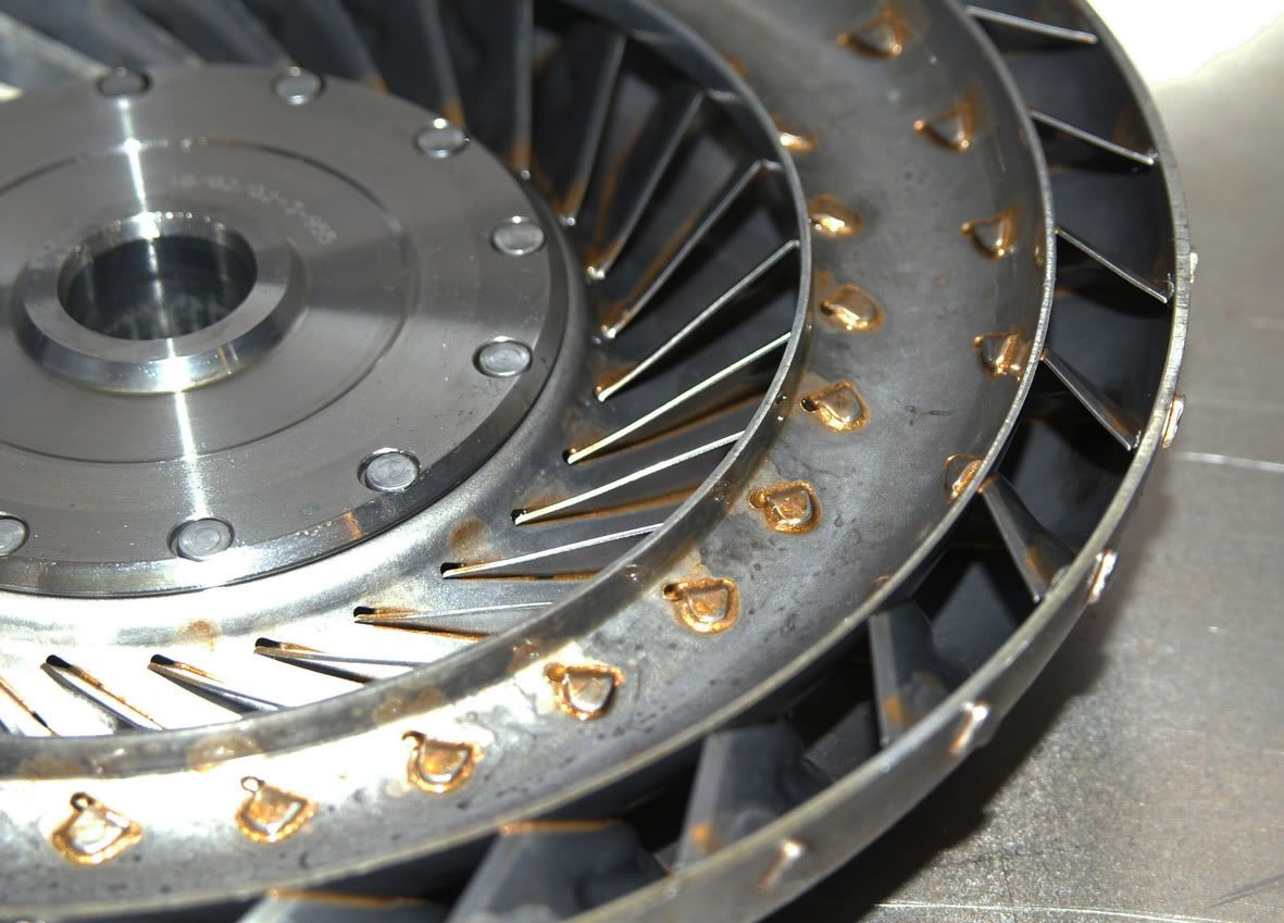 With the turbine lifted out the stator and impeller can now be seen : 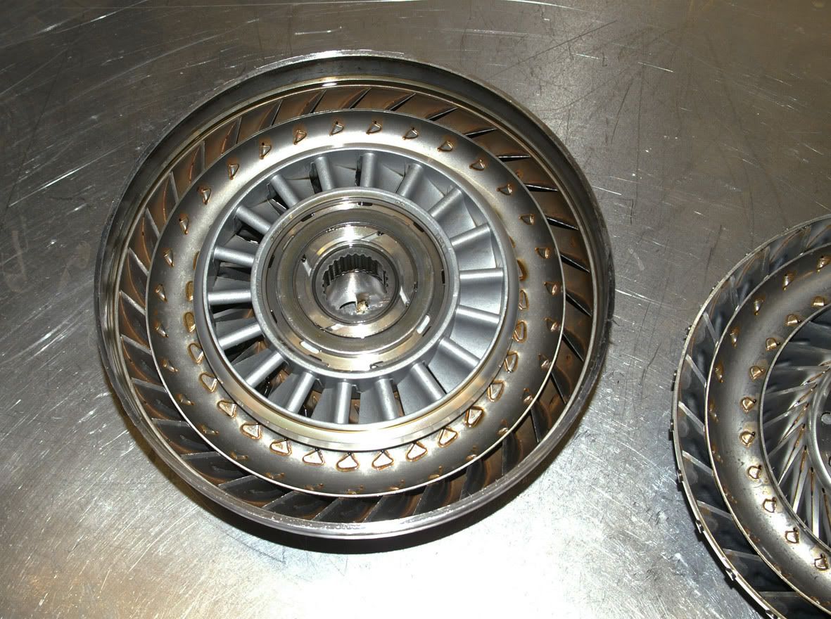 The stator has an axial thrust bearing either side of it, both of which appear to be in good condition : 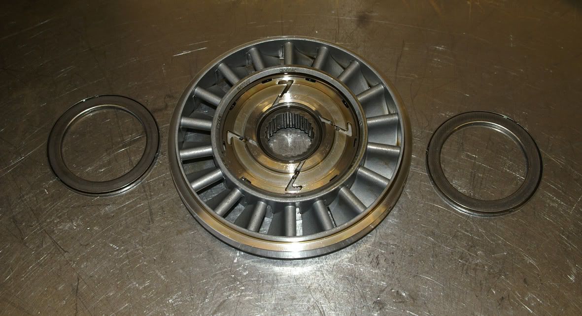 and removing the centre cover reveals the roller-and-ramp one-way clutch which allows the stator to back-paddle once the converter’s coupling point has been reached (at around 85% speed ratio) 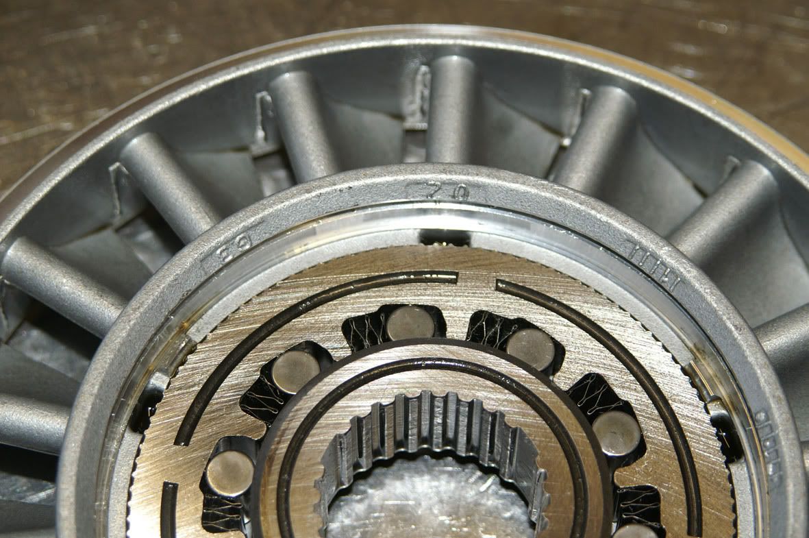 And finally, after removing the stator, the impeller in all its glory :  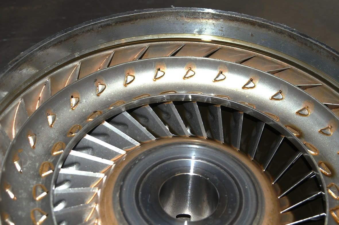 So, clearly an issue with the lock-up clutch lining but the remainder of the converter appears to be in good condition. Anyway, I now need to strip down the sub-assemblies – especially the valve block, where I suspect I will find the root cause of the failure....... Phil |
| Bookmarks |
|
|
|
|