
|
|
|
|
||||||||||
| Xoutpost server transfer and maintenance is occurring.... |
| Xoutpost is currently undergoing a planned server migration.... stay tuned for new developments.... sincerely, the management |
 |
|
|
LinkBack | Thread Tools | Display Modes |
|
|
|
#1
 08-27-2013, 02:06 PM
|
||||
|
||||
|
If you ever sell it the next owner will go nuts trying to figure out what is going on with lights, windows and doors and what all this extra hardware is all about.
__________________
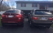
 X5 4.6 2002 Black Sap, Black interior. 2013 X5M Melbourne Red, Bamboo interior X5 4.6 2002 Black Sap, Black interior. 2013 X5M Melbourne Red, Bamboo interiorDallas 
|
|
#2
08-27-2013, 02:18 PM
|
||||
|
||||
|
well, he will probably be left with a lot of unknown wires with factory plugs (since i am using the factory plugs, my newfound fun - i have replaced my previous connectors with the OE connectors), because i will be removing the modules but not the wires...

|
|
#3
10-30-2013, 12:00 PM
|
||||
|
||||
|
41. Installed a home made AUX cable as I was too cheap to pay $60 for 3 wires...
parts 61136931929 - the 3-pin connector, about $1.75 from BMW of Fairfax 61130006664 - male pin, comes with about a foot of brown wire attached from a dealer, I use a Digi-Key part WM2515-ND radio shack part 274-246, about $3, the 3.5 stereo input jack one 300 KOhm resistor, 1/4 watt is good two 20 nF capacitors 3 pieces of 20-24 gauge wire - i used black for ground (factory color is brown), red for right and white for left audio channels... the resistor and the capacitors are the components that will tell the car that the AUX input should be activated - for the sake of argument, say you want to build a 6ft long harness (you are not limited in the length, it can be longer, or shorter, depending on your particular needs). You take 6 feet of each wire and terminate one end of each wire with the 61130006664 - male pin, comes with about a foot of brown wire attached from a dealer, or a Digi-Key part WM2515-ND. this end of the three wires with terminated pins will be going to factory connector 61136931929, which will connect to the pre-wired connector behind the nav screen (if you do not have nav and/or tv options in your car, you don't need that connector and those terminals, you need different pins). the other end of the black wire from the newly created harness needs to be terminated (crimped, soldered) onto the ground post of the 3.5mm jack. the red and white wires need to be cut in two pieces ( the location of the cut is determined by the installer, based on the fact where he wishes to solder in the resistor and the capacitors.) the ends of the newly cut wires are soldered onto the terminals of 300 kOhm resistor - now you will have previously terminated 3 wires (black wire is not cut, thus - the longest) with red and white wires joined with each other via a resistor. then we take one of the capacitors and solder one end of the capacitor onto the end of the red wire, where the resistor is already soldered in. then we solder the other end of the capacitor to the remaining length of the red wire. Then we are doing the same operation with the white wire, solder one end of the second capacitor to the other side of the resistor and solder the second leg of the capacitor to the remaining white wire. then we solder the free end of the red wire to the right channel post of the 3.5 mm jack and the white wire - the left channel post. This is an oversimplified explanation of the harness building for the AUX input and this explanation assumes that the installer has some hands on experience and knowledge in wire cutting, handling of electronic components, soldering and adheres to certain standards of worksmanship. the wiring diagram is posted in the PDF file along with the factory retrofit parts and instructions. in verbal description, the resistor is used by the car's stereo system to detect the AUX input (load of 300 KOhm) and the capacitors are used to isolate that resistor from the audio equipment that will be plugged into the jack... very simple... In my case, I run the wire to the central console, and it will be mounted in the tray that held the CDs ( i have the CD brackets removed for another project). Here I will use a "Screw Cover Hinged", 1/4" Black, UPC code 0-08236-71424-1, to cover up the AUX jack. The cover makes it look somewhat factory, as it covers up the jack... $0.68 + tax at my local LOWE's. Last edited by TerminatorX5; 01-17-2014 at 09:27 PM. Reason: inserted Digi-Key part number and factory AUX retrofit instructions
|
|
#4
01-14-2014, 07:09 PM
|
||||
|
||||
|
Quote:
__________________
2006 X5 Sport 4.4i
|
|
#5
01-14-2014, 11:02 PM
|
||||
|
||||
|
Quote:
however, if you do not have BM53/54 and the navigation, that means that you have the business radio in the dash with all the pins behind the dash - so, you still would have to mess with the front dash... I updated the post that has the item 41 to include the Digi-Key pin numbers and the factory AUX retrofit instructions in PDF (post 33 of this thread)
__________________
E53 X5 4.6iS 147K mi - Sold May 2013 Tireprints left in: USA, Nicaragua, Costa Rica, Panama, Russia  E53 X5 4.8iS built 2005-10-17 66200 mi - June 2012 96000 mi - June 2013 112000 mi - June 2014 OEM fire extinguisher OE first aid kit OE tow hitch OE TV module OE aspheric mirror K&N air filter black/white badges rear camera 4-channel video recorder Here is the list of things I have done to the X
|
|
#6
01-15-2014, 12:32 AM
|
||||
|
||||
|
Quote:
__________________
2006 X5 Sport 4.4i
|
|
#7
10-31-2013, 10:39 PM
|
|||
|
|||
|
You guys are killing me! Been trying to catch up with basic maintenance and I see you guys doing all sorts of cool mods that are tempting me to raid the maintenance fund!!
__________________
04 X5 3.0i auto 03 X5 4.6is
|
|
#8
11-01-2013, 11:59 AM
|
||||
|
||||
|
Quote:
__________________
X5 4.6 2002 Black Sap, Black interior. 2013 X5M Melbourne Red, Bamboo interiorDallas
|
|
#9
11-03-2013, 02:28 PM
|
||||
|
||||
|
26. Installed the AV input for the factory TV module - the TV module itself is not good for any TV in the USA, but it has the factory rear camera input, and also it has the AV in and out...
Last edited by TerminatorX5; 11-03-2013 at 02:45 PM.
|
|
#10
12-09-2013, 05:10 AM
|
||||
|
||||
|
Quote:
This is not entirely true, LOL. TV is possible in the USA. I have it in mine. What is not possible is TV while moving.
__________________
2010 X6 50i 2005 X5 3.Oi, Many Options  2015 HONDA CR-V EX-L 1998 ACURA 2.5TL MODs - Driver's outside mirror light - Voice Recognition Module - Blaupunkt Entertainment System with Digital TV
|
|
| Bookmarks |
| Thread Tools | |
| Display Modes | |
|
|
|
|











 Hybrid Mode


