
|
|
|
|
||||||||||
| Xoutpost server transfer and maintenance is occurring.... |
| Xoutpost is currently undergoing a planned server migration.... stay tuned for new developments.... sincerely, the management |
 |
|
|
LinkBack | Thread Tools | Display Modes |
|
#1
 03-11-2015, 10:40 AM
|
|||
|
|||
|
35d Intake Manifold DIY with pics for CBU, glow plugs
Youll need what I consider the usual assortment of sockets, plus hex sockets, torx sockets, and e-torx sockets. An extra long set of hex sockets/wrenches would be handy. A mirror to see connections at the back of and underneath the intake manifold is essential. Torque wrench is needed for re-assembly. A fair number of electrical connections will be dealt with, so I recommend tagging each disconnected cable/connection with blue painters tape so they will (hopefully) not be missed during re-assembly. I am just a hobbyist, not a BMW tech - so its possible that I may say some things that are completely wrong. Im not responsible if you have a problem, proceed at your own risk, and so on, and so forth. To begin with, remove the acoustic cover (large top most piece of plastic on the engine - part # 1 in the Realoem link below) on the top of the engine. Just tug it upwards and off. 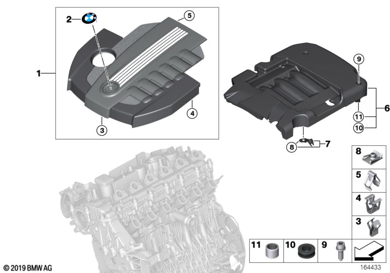 Remove the air duct at the proximal end of the intake muffler (part # 12 below), and the mass air flow sensor that is at the distal end of the intake muffler (part # 1 below). The bottom torx screw that connects the MAF to the intake muffler is surprisingly difficult to reach. One good option is to use a flexible drive for the torx bit (Amazon link is http://www.amazon.com/Anytime-Tools-.../dp/B00129IG7W ). Another option is to lift the intake muffler from the 4 press fittings (see next paragraph) and tilting the rear of the intake muffler up in the air - thus making it much easier to reach that bottom torx screw. If you do this, youll need to remove the MAF electrical connection (part # 17) to allow the position of the intake muffler to be shifted.  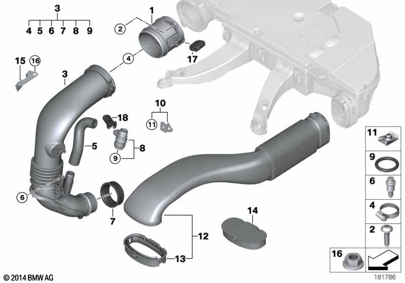 The intake muffler (part # 1 below) is held in place by four press fittings - one at each of the front legs and two in the rear (near firewall) of the intake muffler. The intake muffler can be removed with a solid upward tug in the area of each press fitting.  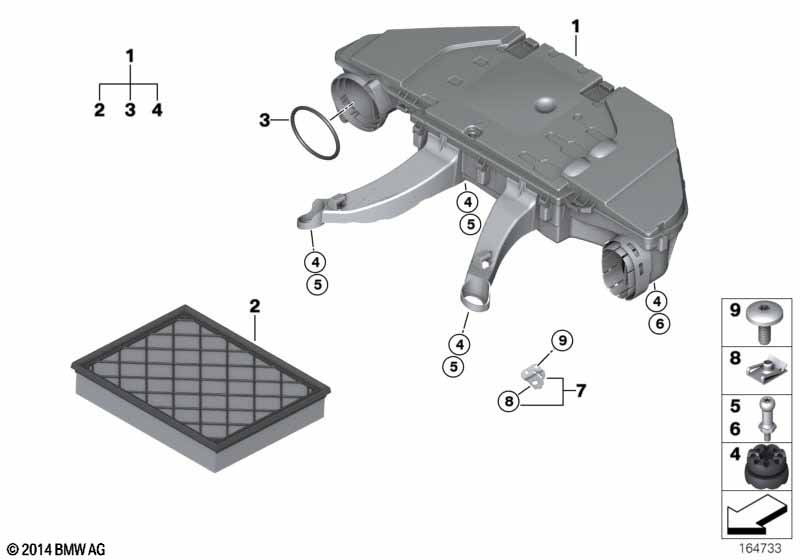 The intake manifold is covered by a grey sound proofing molded foam block (part 6 in the Realoem link below). The rear portion (toward the firewall) has an additional black plastic cap (part 9 below) over the foam block. Two hex bolts hold the black plastic cap in place. Remove the bolts, and the cap and molded foam can be removed. The plastic cap is a tight fit to wiggle out under the various brackets, but work at it gently and diligently and it should come out nicely. The intake manifold has some hidden connections back near the firewall as well as on the side and bottom that need to be removed. The pic below lists the ones to deal with now. The white arrow below points to where an electrical connection goes to the fuel line - not visible in this photo, but can be seen in the mirror reflection on the next photo. The blue arrow below shows where the brake hose boost bracket is connected to the intake manifold. Again, it is not visible in this photo - you will need to use a mirror to view the nut/bolt/bracket. The yellow arrow below points to the intake manifold pressure sensor electrical connection. The green arrow below is the brake booster hose - it will lead to the bracket discussed above near the blue arrow. The red arrow below is the oil dipstick guide tube bracket. Disconnect all of the above. The fuel pressure sensor connection (white arrow) does not actually connect to the intake manifold, but it is in the way of one of the intake manifold tangential nuts (see second picture below), so I found it easier to get it out of the way. The next picture below shows a mirror being used to visualize between the intake manifold and the firewall. Red arrow shows the fuel rail electrical connection, which obstructs access to the tangential bolt/nut (yellow arrow). To hopefully make this more clear, the next photo shows what things will look like when the intake manifold is out. The yellow arrow is the fuel pressure electrical connection discussed above, the green arrow is the tangential bolt discussed above (nut removed, bolt remains), the blue arrow is the brake boost bracket discussed in the first picture, and the red arrow is the oil dipstick guide bracket. Be aware that there is still another electrical connection (leads to the swirl motor on the bottom of the intake manifold) that will need to be disconnected, but that will be much easier to reach later when the intake manifold position can be tilted/shifted a bit. More on this swirl motor electrical connection later. Next, a conceptual discussion. The intake manifold is bolted to the engine with 12 bolts and 7 nuts (to be shown in pics later). Those are pretty easy to get to. But what I believe is more of a challenge is getting the intake manifold disconnected from the EGR valve/throttle body. Some of those bolts are on the underside and hard to get to. What is easier (in my opinion) is to remove a number of easily reachable bolts, and then remove the intake manifold/EGR valve/throttle body as a single unit. Doing this as an en bloc resection is much easier (IMO) than struggling to get to the hidden lower bolts. If you have some extra long hex wrenches/sockets with swivel adapters, you could remove the EGR valve/throttle body separately from the intake manifold. However, my opinion is that its easier to do the en bloc resection. Once the intake manifold/EGR valve/throttle body is out, it is simple to reach the bolts that allow separation of the intake manifold, EGR valve, and throttle body. For now though, attention is turned to the front of the engine, and dealing with the charge hose/throttle body/EGR valve. The charge air hose/line (part # 12 below) needs to be removed from the throttle body. Pull off the clip (I had to remove it completely, otherwise it would hit the EGR cooler and not allow the hose to come off) and slide the charge hose back and off the throttle body.  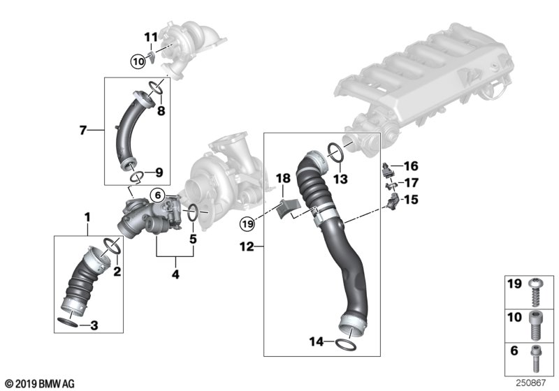 Check out the photo below to get an overview of what needs to be done: Be aware that this picture was taken after re-assembly to document the disassembly process. Therefore, when you are at this point of the repair your view will be slightly different. The black plastic leg of the intake muffler will be out of the way, and the thick grey soundproofing foam that is covering the intake muffler will also be out of the way. Nonetheless, the yellow arrow shows the clip that must be completely removed to allow the charge air hose to be removed. The green double arrow shows the electrical connections to the throttle body and EGR valve that need to be disconnected (these connections are on the same wire bundle - the throttle body connection is easily visible right on top, but the EGR connection is to the side and below -not visible in the photo. The second green arrow points in the direction of the EGR connection, but it is not visible in the photo). The blue arrow points to a wire bracket that needs to be removed that holds the wire bundle going to the EGR valve. Remove the circumferential clamp (black arrow) that connects the EGR cooler to the EGR valve. The red arrow points to an EGR cooler electrical connection that I found surprisingly difficult to disconnect. I thought that when I slid the white tab back that it would disconnect easily. Not so at all - at least not for me. Several other forum posters have noted that this connection was difficult, so at least its not just me. Anyway, what I found that works well is to slip a flat blade micro-screwdriver on the bottom of the connection clip area from the back side and push forward to release the clip mechanism. The photo shows the tip of a micro screwdriver in position to do this. Edit on June 11, 2016 - a helpful poster has demonstrated how to remove this clip - once you slide the white clip back, then squeeze it with a pair of pliers. The squeezing of the clip at one end lifts the locking mechanism at the other end, and it slips apart easily. Easy - once you know the trick! So now were getting close to getting the intake manifold off. There are a couple of brackets that help stabilize the EGR valve and throttle body that need to be removed (parts 7 and 18 in the Realoem image below). Check out this image from Realoem:  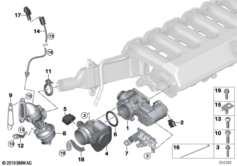 For orientation, part 4 is the throttle body, and part 1 is the EGR valve. Note that part 5 and part 2 are the electrical connections that were represented by the double green arrow 2 pictures above. The brackets that need to be removed are part 7 (connects two EGR bolts to one of the intake manifold tangential bolts), and part 18 (helps stabilize the throttle body/EGR assembly to the engine). Just to make things complicated, part 18 was added as part of a service campaign to reduce EGR cracking and (if you havent had service at a dealership in a while) may not be in place on your car. This link discusses the campaign/clamp/bolts in detail. Pay particular attention to the instructions in the service bulletin surrounding the second picture. The idea is that during re-assembly the throttle body/EGR valve/EGR cooler/clamp need to be all aligned properly and in a neutral position before tightening the bolts to 8 Nm. The fear is that if some of the parts are tightened down in a twisted or mis-aligned position, then undue stress might be placed on the EGR cooler -leading to cracking/failing in the future. Also, if you have an older car and havent had the service done, you might not even have the part # 18 clamp. In which case, you can choose to make an appointment at your dealership for your free upgrade. Assuming you have had the service bulletin performed, remove the 10 mm bolt that holds the clamp to the engine - this is shown in the Realoem image as where part # 19 goes through the clamp. Now the clamp will be able to be removed en bloc along with the throttle body/EGR valve/intake manifold. One more bracket needs to be removed before going after the manifold nuts/bolts themselves. Part # 7 in the Realoem image is a bracket that stabilizes the EGR valve/intake manifold connection by also attaching to one of the intake manifold tangential nuts. This picture hopefully shows it clearly: Remove the two hex bolts (red arrows) that hold together the bracket/EGR valve to the intake manifold. The yellow arrow points to the nut that stabilizes the bracket to the first intake manifold tangential bolt. Remove this nut. The green arrow points to the bracket itself (part # 7 in Realoem). This bracket is now free. The EGR valve/throttle body/throttle body clamp unit is still attached to the intake manifold by two bolts on the bottom of the EGR valve that are very hard to get to (unless you have an extra long hex socket). Those bolts will be trivial to reach once the manifold is out. A brief discussion on terminology: Remember that air in the intake manifold will enter the enter engine via one two intake paths - either the top swirl ports, or the tangential ports. Swirl flaps in the intake manifold control the relative ratio of swirl/tangential air. In turn, the swirl flap motor is controlled by an engine computer. The reason I go into this is that I will term the nuts/bolts around either the swirl port or the tangential port as a swirl bolt or a tangential nut. Clear as mud, right? Here is a picture of the twelve swirl bolts all marked by red arrows. Remove them. Be aware they are M6 bolts, and when replaced need 10 Nm torque. Some sites have said all intake nuts/bolts can be torqued to 15 Nm, but I do not agree. BMW recommends M6 torque to be 10 Nm. And I found several references to sad people who had snapped M6 bolts while torquing to 15 Nm. When removing the swirl bolts, you will note that the bolt that is third from the rear has a bracket attached to it. This bracket is what is used to attach the rear plastic case that sits on top of the grey soundproofing material. During re-assembly, dont forget about this bracket. Next, remove the seven tangential nuts shown by the red arrows in the pic below. Actually, the first (most forward) nut was removed earlier when removing the EGR valve bracket discussed above. Be aware that these are M7 nuts, and can thus be torqued during re-assembly to 15 Nm. Sorry for being repetitive, but remember the different torque values for the M6 bolts, and the M7 nuts - dont snap anything. The intake manifold can now be worked loose from the engine. In my case, it needed a thin paint scraper to be worked in around the swirl port/intake manifold juntion. Careful, gentle, symmetrical pressure around the intake manifold and it loosened right up. The intake manifold/EGR valve/throttle body/throttle body clamp assembly can be lifted/shifted/tilted, but cannot quite come out yet - it is still attached by an electrical connection to the swirl motor. This electrical connection is a little tricky. Here is a picture that I hope will make this easier to understand: The above picture shows the bottom side of the intake manifold after removal. The green oval shows where the electrical connection is made to the swirl motor. Unfortunately, the spring loaded post next to the connection made it impossible for me to get a finger in position to depress the locking tab and remove the connection. What I did was tilt/shift the intake manifold so that I could slip a micro screwdriver into the locking tab mechanism from the back side of the electrical connector (this is simulated by the red arrow in the picture). So the intake manifold is lifted/tilted/shifted to provide reasonable access. I used a micro- screwdriver in my left hand to release one locking tab (simulated by red arrow), while simultaneously using my right hand to squeeze the other locking tab and pull off the connection. And I was standing on one foot while chewing gum, too! I kid, I kid. Anyway, now it should lift out nicely. Whats the big deal? Once out, it is trivial to separate the EGR valve/throttle body/intake manifold. Besides the intake manifold/EGR valve/throttle body, one now has easy access to glow plugs, and glow plug control module. When re-assembling things, I recommend using this opportunity to replace various gaskets: 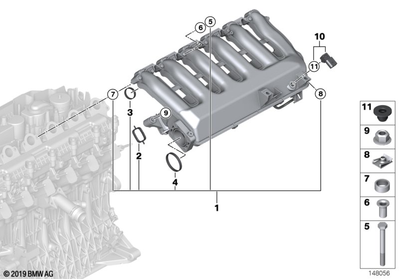  Part 2 is the tangential port gasket #11617790198 - youll need 6. Part 3 is the swirl port gasket #11612246945 - youll need 6. Part 4 is the EGR valve seal #11612245439 - youll need 1. Part 11 is the grommet for the sensor # 13627792261 - youll need 1. Youll also want the O-ring between the throttle body and EGR valve - not shown in the above image #13547792098 - youll need 1. Feel free to replace the intake manifold nuts and bolts if you want, but I did not. Remember the torque values noted above for the intake manifold M6 bolts and M7 nuts. Remember to have the intake manifold/EGR valve/throttle body/throttle body bracket in a neutral position before tightening to the 8 Nm as discussed in the service bulletin noted above. You dont want a twisted re-assembly contributing to a cracked EGR cooler. Its really not too bad of a project. Knowing ahead of time a few of the issues discussed above, Id put it at 5-6 out of 10, with roughly 2 hours for disassembly, and 1.5 hours for assembly (moving slowly and carefully). Hope the above is helpful.
__________________
Stephen 2010 e70 35d- now driven by son #2 2005 e53 3.0 - now driven by son #1 2021 G05 45e PHEV - now driven by me 2008 ML320 CDI - driven by wife Last edited by sgrice; 06-12-2016 at 07:28 AM. 
|
| Sponsored Links | |
|
|
|
|
#2
03-11-2015, 12:05 PM
|
|||
|
|||
|
Excellent write up sgrice.Thanks for taking your time to write this DIY.
|
|
#7
08-06-2018, 02:53 PM
|
||||
|
||||
|
Thank you for this guide! I used it to delete the swirl flaps.
__________________
2012 X5d | Deleted & BRR Tuned | DWR TCU Tune | 10.25" Android 8.1 Screen Build Log https://xoutpost.com/bmw-sav-forums/...efinished.html
|
|
#9
08-27-2018, 12:59 PM
|
|||
|
|||
|
New member here! This write up was amazing. Hoping someone can help...
I just performed an EGR delete with JR Tuning Stage 2 + EGR delete reflash. I took the intake manifold off, cleaned it, deleted the swirl flaps, and reinstalled. Since I took out the EGR and EGR cooler, decided to replace the thermostat since it was easily accessible. Now it won't start (it cranks fine but won't turn over). I rechecked everything, reseated the ecu, checked the fuel pump relay, made sure all plugs were in and secure. I recharged the battery just in case. It almost feels like fuel isn't getting sent to the rail (and yes, I made sure the fuel rail pressure sensor was plugged back in). I'm at a total loss, not sure what to do other than get it towed from my garage to a mechanic. Anyone else have this issue? I don't think I need to bleed the fuel lines because I didn't mess with that at all (didn't mess with injectors or glow plugs). Any help would be sincerely appreciated. 2011 X5 35d
|
|
#10
08-27-2018, 01:03 PM
|
||||
|
||||
|
was it driving fine before with the tune?
__________________
2012 X5d | Deleted & BRR Tuned | DWR TCU Tune | 10.25" Android 8.1 Screen Build Log https://xoutpost.com/bmw-sav-forums/...efinished.html
|
|
| Bookmarks |
|
|
|
|


 Linear Mode


